VALVE SPRING TECH
The humble valve spring might appear to be a relatively simple piece of engineering, but in reality it can be the most highly stressed component in a race engine. The move to faster engine speeds and more aggressive cam profiles can often result in terminal failure of the springs leading to catastrophic engine failure, prompting spring replacement earlier than preferred. Engine builders and manufacturers are therefore focusing more and more efforts on ways to increase the life of the spring to avoid costly engine rebuilds.
In essence, the prime function of the spring is to provide a force that will keep the reciprocating movement of the poppet valve under control throughout the entire cycle of the engine and at all operating speeds. Loss of this valve control can lead to valve-to-piston contact, extreme loading of the seat in the cylinder head, bouncing of the valve on the seat and damage to the tip of the valve.
A compression spring like those found in engines provides a reactive force when its length is reduced, predominantly owing to a twisting motion of the coiled wire. Under just a static load, it can be assumed that the load in each coil is identical, and if the coil geometry is uniform along the spring axis then the stiffness of each coil is also identical. The highest stress will occur on the inside diameter of the spring, which is where one could expect failure to originate from.
Spring Surge
Of course, when the engine is running, the linear motion of the valve imparted by the rotation of the cam lobe causes a continuous compression and expansion of the spring. As a result, the dynamic loading on the spring has to include the inertia of the spring, which is not considered under static loading. It is the dynamic loading from the inertia that will result in the most common of spring issues, namely spring surge.
Spring surge can be described as vibration of the spring that occurs at a harmonic of the spring’s natural frequency. When describing surge, the movement of each particle of the spring needs to be considered, and in a way this movement of each coil can be seen visually with a child’s Slinky toy spring.
During the initial opening phase of the lift curve, the spring is compressed and the spring coils accelerate. The uppermost spring at the camshaft end will see the entire inertia of the spring, but each successive coil sees less inertia loading thanks to the lower mass below it and lower acceleration due to a smaller deflection. As a result, as we move down the spring away from the camshaft, each coil accelerates and moves at lower values than the one above it. This begins the first compressive wave of the coils, with the camshaft end closing up quickest.
At around the mid-point of the travel of the valve, its acceleration is zero, and at this instant the coils all move at the same speed. Then, as the valve begins to decelerate, the coil furthest from the cam starts to close up more than those above it, creating a compression wave going in the reverse direction. It is this continual cycle of the compression wave that creates a vibration in the spring and is referred to as surge.
Preventing Surge
Whilst there are numerous tricks to reduce or even eliminate surge, the most obvious one is to create a spring with a natural frequency well outside of the running range. The movement of the valve is dictated by the profile of the cam lobe, and can be mathematically broken down into a series of sinusoidal curves with Fourier analysis, from which the harmonics of the profile can be derived, which are expressed as multiples of the camshaft rotational speed.
When one of the harmonics coincides with the spring’s natural frequency, the effects of surge will be pronounced and can result in the compression wave spiralling out of control, leading to loss of contact between the spring and the retainer and spring seat at either end, plus the build-up of excessive stresses in the coils. As the amplitude of the lower harmonics are larger than those of the higher harmonics, some spring designers will recommend that the natural frequency of the spring is at least eight times the frequency of spring operation, whilst some technical publications quote 15-20 times.
Wire Geometry
The cross-section of the wire is usually circular or ovate; the latter term actually means egg-shaped, but in the case of springs this can also be any elliptical shape made up from a number of radii, and can be either symmetrical or non-symmetrical. An ovate spring will typically have the major axis perpendicular to the spring axis, which helps to reduce the stress on the inner diameter as the maximum area of the wire is at the point of highest stress, and can lead to a shorter spring length owing to the wire being slightly flattened.
However, some of the higher grades of steel do not work well with the dies used to make the ovate wire shape, as the additional carbon can extrude the special dies needed to form the more complex cross-section. Consequently, the round wire can be made with more carbon content than an ovate wire. It is also harder to control the orientation of the ovate profile when coiling the spring, as it will have a tendency to twist down the length of the spring during coiling. In fact, changing the external shape of the spring can have a far stronger effect on the life of the spring than using an ovate cross-section.
Spring Shape
Nowadays there are a myriad of options available for the external shape of the spring’s helical coils, although they can be broken down loosely into three categories: straight, conical and beehive.
Conical and beehive springs are termed as progressive, as the stiffness will vary with length. This is also a case for springs with an unequal pitch between the coils along the length of the spring. In progressive springs, each coil has a different stiffness, which means that when the spring is compressed, the coils with a lower stiffness will deform more than those with a higher stiffness. Eventually the less stiff coils become coil-bound (where adjacent coils come into contact), which reduces the number of active coils available as the load is increased, increasing the overall stiffness of the spring in a progressive manner. As the stiffness is varying, so too is the natural frequency, hence in theory progressive springs are less susceptible or even immune to the problem of spring surge.
Both beehive and conical springs also have an advantage over a straight spring in that the retainer can be smaller, which in turn can lead to reduced valvetrain reciprocating mass. The springs themselves can also be lighter, and so the inertia of the upper coils will be lower. One final observation made by a spring supplier is that conical springs can also have a natural alignment action that is very beneficial for very small valve stem diameters.
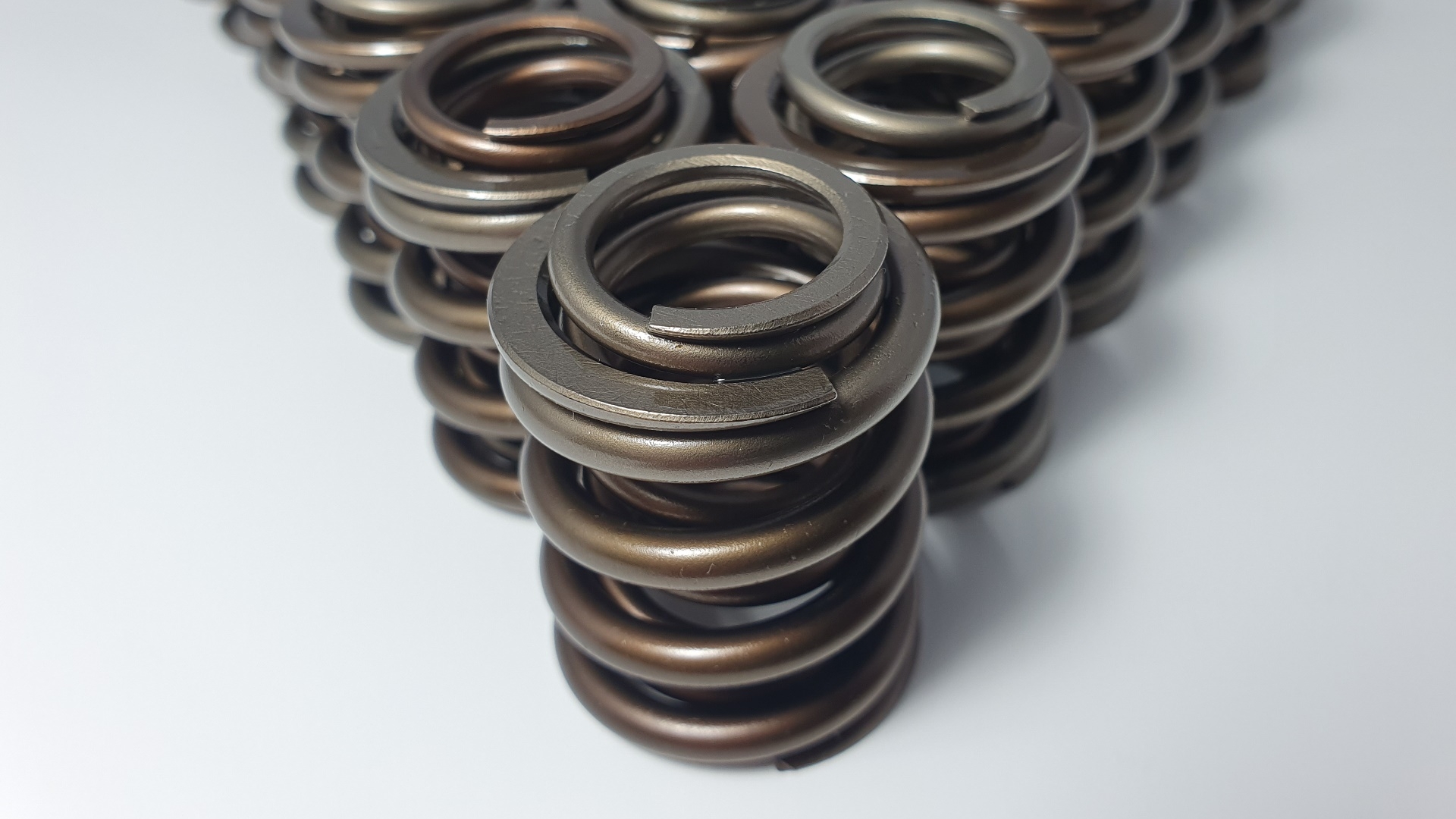
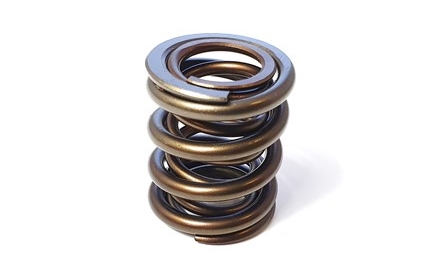
Nested Springs
Another solution to surge is to use nested springs, where two or three springs are used in parallel, with smaller springs packaged inside larger ones. As with progressive springs, the stiffness of the combined spring varies with length, and each spring will have a different natural frequency, again helping to avoid surge.
The outer diameter of the inner spring and the inner diameter of the outer spring are usually chosen so as to create a small amount of interference between the two springs (as is the case with our DFV valve springs). It is essential that the direction of windings is different between the springs, otherwise they will get caught up in one another. The interference will provide a means of damping, allowing unwanted energy to be converted to heat from the friction between the two springs.
When run for extended periods, this interference will of course wear the surfaces of the springs and reduce the life of the nested spring assembly. Owing to titanium’s inherent nature to gall (the macroscopic transfer of material between metallic surfaces) when in contact with other titanium surfaces, titanium nested springs cannot be run with interference.
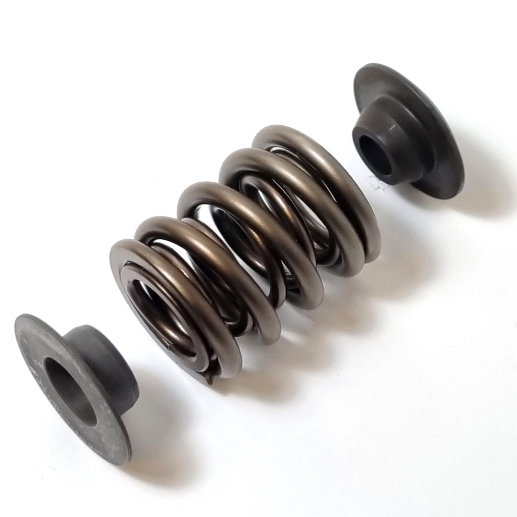
Where the designer wants to avoid contact between the inner and outer springs, stepped retainers and spring seats can be used. This will separate the two springs to eliminate friction and hence damage to the surfaces.
The size of the spring is determined by multiple factors: the cam profile and associated lift, acceleration rates and opening, closing, flank, nose and seating velocities; valve train masses; the moment of inertia of the rocker (if present); the operating speed of the engine. All of these parameters will give an idea of the required amount of spring travel, spring force and spring rate that is going to be required to control the valve at speed.
Materials
Because of the high stresses that the spring will experience, special care has to be paid to the cleanliness of the raw material, the surface finish and any methods that can be used to leave compressive residual stresses in the surface that would counteract the stresses from running.
When choosing a material, spring manufacturers will look at its torsional modulus of rigidity and torsional yield strength, as well as the more practical requirements such as cost and availability. Most compression springs are made from steel or titanium drawn wire, with the former being more common.
The actual chemical composition of the steel alloys used by spring manufacturers remains a closely guarded secret, which is understandable given the intense amount of research and testing they carry out to find the perfect mixture of elements. However, what is known is that most steel alloys used in spring manufacture will contain chromium and silicon. Vanadium is also included at small levels to increase the strength of the material, along with manganese, molybdenum and nickel in some cases.
Titanium springs are usually made from Beta-C and LCB (Low Cost Beta) titanium alloys. Titanium can offer the benefit of lower density and higher strength, plus better resistance to corrosion when compared with steel. However, its cost can often mean that that titanium springs are about five times more expensive than their steel counterparts. Also, some of the steel alloys used nowadays have proven to have higher fatigue limits than the titanium alloys available.
Manufacturing
The manufacture of a steel valve spring starts with the material being rolled into rods by a specialist steel mill, that is capable of producing the level of cleanliness required for racing.
Some steel mills will take extra steps to ensure that any inclusions in the microstructure are pushed into the centre of the wire, where the stresses during running will be lower. Also, great care is taken to make the inclusions smaller (it is the inclusions that can make the wire brittle), giving rise to the term ‘superclean’ chrome-silicon as used by some steel mills.
The wire is drawn down to size by pulling the rod through a series of dies, all the while being tested and scrutinised in line with the manufacturer’s quality standards. Attention is paid to tensile strength, surface inspection and chemical analysis, and eddy-current testing is used to verify the surface (an electromagnetic field is created around the wire to allow for microscopic identification of any surface defects such as pitting, cracks and corrosion).
Some spring manufacturers will also use scanning electron microscopes (SEMs) and X-ray diffraction machines (XRDs) to check for material integrity. An SEM allows metallurgists to view the surface topography and composition, while an XRD can measure compressive residual stresses. Such methods can be incorporated into various stages of the manufacturing route of the spring to ensure no degradation in quality.
The wire is then shaped into the designed helical coil pattern using CNC machines to control the winding of the wire onto mandrels, with the wire being either hot or cold. The use of such complex machines allows for better repeatability between batches of springs and improved accuracy in the pitch and diameter of the coils. Next, the spring has to be stress relieved. The coiling stage permanently deforms the wire, creating harmful residual stresses, and so a heat treatment operation at a relatively low temperature is needed to remove them. Note that coiling is more complicated when the wire’s cross-section is not circular.
With the shape of the spring now complete, attention is then paid to the ends of the spring. It is imperative that the end faces of the spring are perpendicular to the axis of the spring and parallel to each other so that the forces will be evenly distributed in the valve stem. As a result, the ends are ground. As the grinding can leave sharp edges, a finishing step is carried out to remove uneven areas on the surfaces of the ends. Without this final operation, the edges could break away into the cylinder head chamber or dig into the retainer and spring seat, creating fatigue crack initiation sites.
Surface Treatments
At this stage, there are numerous processes that spring manufacturers will carry out to increase the life of the spring. We will look here at shot peening, nitriding, polishing and cryogenic treatment, but there are numerous other techniques that manufacturers are less willing to reveal, for obvious reasons.
Owing to its cost-effectiveness and practicality, shot peening is a relatively common technique to impart a compressive stress in the surface. Here, small spherical beads made from steel, glass or ceramic are fired onto the faces of the spring in a controlled manner. The impact of each bead will create a dimple in the surface, stretching it, and below the dimple the movement of the material creates the compressive stresses required.
There are three parameters that can be varied to alter the magnitude and depth of the compressive stress – bead size, intensity and coverage. In general smaller size beads will yield a more polished surface. The intensity is the amount of energy used to project the beads, while the coverage is the amount of area that is impacted by the beads (note that this is always more than 100%). All these variables will depend on the material of the spring and any subsequent processes.
Nitriding is a heat treatment procedure that will diffuse nitrogen into the surface of the spring to give a case-hardened surface and can also impart a compressive stress into the surface. A harder surface is especially useful in a nested spring design, where there is interference between the springs.
In gas nitriding, the spring is placed in an oven at temperatures of about 500°C for a period of time while ammonia is flowed around the spring’s surface. The alternative to gas nitriding is plasma nitriding. Whereas gas nitriding relies on a high temperature to create a reaction with the surrounding gases, plasma nitriding uses intense electric fields to create ionised molecules of the gas (usually nitrogen) around the spring’s surface. Note that if a spring is to be both shot-peened and nitrided, the nitriding step is carried out first, otherwise the high temperatures during nitriding would relieve the compressive stresses induced at the shot-peening stage. The added advantage of nitriding first is that the substrate is harder, so the compressive stress from shot peening is increased.
One or more refinement procedures are also usually carried out to remove any remaining surface defects and imperfections, both between certain operations and at the end of manufacture. Electro-polishing is one such method that has been proven to be beneficial, although it can lead to hydrogen embrittlement, to which the high-strength alloys can be susceptible. However, a combination of chemical and mechanical isotrope finishing is becoming more common, and this creates a polished mirror-like surface without the issues seen with electro-polishing. Some manufacturers will go even further after polishing by adding a final peening operation with minute beads (often referred to as micro-peening or nano-peening).
A final operation carried out after all or some of the above is to pre-set the spring. Here, a relatively large load is applied to the spring, such that while the centre of the wire is elastically deformed, the surface of the wire undergoes plastic deformation. This procedure will set the free length of the spring, as the plastic deformation means that the spring will not return to its original length. Pre-set springs are less likely to relax over time, and if the pre-setting is carried out at a controlled elevated temperature than the spring will be more capable of withstanding service in hot environments too.
Installation
Despite every effort in design and manufacture to increase the reliability of valve springs, spring suppliers see a surprising number of failures due to improper installation. One of the more common issues they see is incorrect design of the retainer. The spring needs to be correctly contained in the retainer to stop it from excessive lateral movement, but not overly constrained such that it is forced into the retainer.
Handling the springs also has to be done with care to avoid damaging the surface. They should never be placed in a vice or pliers, and plastic tooling should be used when separating interference-fit nested springs. Also, springs that have been delivered with a rust preventative coating should not be cleaned with acidic or evaporative cleaners, as this can cause rapid drying and promote the formation of rust on the surface of steel springs.
A static spring testing machine can be used when selecting and fitting valve springs to confirm the rate of the load versus deflection; such machines can detect the onset of binding of the coils.
Summary
The life and maximum operating envelope of many race engines is restricted by the valve spring. While it is possible to extend the life of the spring by reducing engine speed or compromising on cam profiles to lower the acceleration of the valve, there are numerous methods available in the design and manufacture of the spring that should be considered – wire cross-section, the geometry of the helical shape and a combination of nested springs can all be exploited to reduce or even eliminate certain failure modes. Numerous manufacturing processes exist that will create beneficial compressive stresses at the surface.
This feature on valve springs is based on an article written by Modatek’s Matt Grant for Race Engine Technology, issue 89. You can purchase a back copy of this publication here: https://www.highpowermedia.com/Product/race-engine-technology-issue-089

