An essential stage when designing a crankshaft is to ensure that it is as well-balanced as possible. This is normally done with the addition of counterweights, which will counteract the inertia forces and couples created by the rotating and reciprocating masses. If a crankshaft is not correctly balanced then it can lead to excessive vibration, which will have a detrimental effect on reliability.
At the heart of every piston-powered engine sits a crankshaft, to convert the reciprocating motion of the pistons into rotational movement. The movement of these piston assemblies, connecting rod assemblies and the crankshaft itself creates large inertia forces and couples, which in most engine configurations have to be balanced out with webs and counterweights on the crankshaft. These forces and couples will manifest themselves as vibration, which if ignored can drastically reduce the reliability of both the engine and the car.
Bad Vibrations
A poorly balanced crankshaft can drastically reduce the reliability and performance of an engine. First of all, the out of balance forces will subject the main journal bearings to higher loads than they are designed for. Most main journal bearings are plain bearings, relying on a constant film of oil for lubrication; an increase in load will reduce the oil film present, which in turn will lead to a loss of power. Should the oil film start to break down under excessive loading, then the bearings will wear out quicker than intended.
The imbalance within the crankshaft may cause it to distort (both in bending and in torsion). This distortion also has a negative effect on main journal bearing performance as the edge loading of the bearing is increased.
Externally, the loads from the crankshaft are transmitted to the mating chassis through the engine mounts. It is often not possible to incorporate any damping into these mounts, particularly when an engine is installed onto the back of a single-seater monocoque, so these vibrating loads are passed through to the driver; in the past, drivers have been known to suffer from visibility issues when racing because of badly balanced crankshafts.
Vibration from the engine will also affect the reliability of components mounted to the chassis, from minor ancillary parts through to important structural members. So a car’s reliability can sometimes be greatly improved just by better crank balancing.
Calculation of Balancing Forces
While the primary objective of the crankshaft is to convert the reciprocating motion of the pistons into a rotation movement that will turn the engine’s output shaft, it also has another job to do: to provide opposing forces and couples to balance the forces from the moving parts in the crankcase, thereby reducing the amount of engine vibration.
A perfectly balanced engine would exhibit no vibration, such that it could be suspended in mid-air and not move. Of course, in reality that is almost impossible; however, the dynamic forces and couples can be virtually eliminated for some engine configurations.
As mentioned, the dynamic forces are due to the movement of the internal masses within the crankcase. The masses attached to the crankpins can be broken down into two categories: rotating and reciprocating.
Rotating masses consist of the crankpin bearings, big-end bolts and a proportion of the connecting rod mass that is centred on the crankpin. Also not to be forgotten when considering the rotating mass is that of the crankpin itself, plus any lightening hole bungs that might be present. The reciprocating masses will include those of the piston, gudgeon pin, bush, rings and clips, plus the rest of the connecting rod.
The proportions of rotating and reciprocating masses of the connecting rod are normally expressed as the rod’s big-end and small-end masses, and are derived by taking moments about the rod’s centre of gravity. Assuming that a 3D CAD model of the connecting rod exists then most CAD software packages can quickly give the position of the centre of gravity for the rod. Alternatively, before the advent of CAD, the traditional method to determine the big- and small-end masses would have been to weigh the connecting rod on two scales, with one scale on the split line between the rod and cap and the other on the small-end centreline, whilst keeping the connecting rod centreline horizontal.
Next, consider the reciprocating motion of the piston. The acceleration of the piston can be broken down into a series of sinusoidal waves, which can be expressed as:
where θ is the crank angle from the cylinder centreline, r is the crank throw, n is the crank throw divided by the rod length and ω is the angular velocity of the crankshaft. There are higher-order cosine terms, but these are not normally considered.
It follows that the inertial force Frec created by the reciprocating motion of the piston is:
where mrec is the mass of the reciprocating parts. The first half of this equation is termed as the primary reciprocating force, and the second half the secondary reciprocating force. As these primary and secondary forces act along the cylinder centreline, they will create a corresponding primary couple and secondary couple about the front and rear main journals.
There is also an inertial force Frot and associated couple created by the rotating components, which can be found from the equation:
where mrot is the mass of the rotating parts.
In a similar manner, the inertial forces Fweb from the rotating webs (including counterweights) can also be found, as:
where mweb is the mass of the web (including counterweight) and rweb is the distance from the centre of gravity to the crankshaft centreline. A 3D CAD model can give a very good measure of both the mass and the position of the centre of gravity of each web.
The inertial forces and couples from the webs will only be able to balance out the forces that are occurring at once times engine speed. The secondary forces are occurring at twice engine speed, and so would need to be balanced out by external balance shafts rotating at twice engine speed.
As it is not possible to completely balance out the secondary forces and couples, crankshaft designers often cite a balance factor, usually as a percentage. That is the percentage of the reciprocating mass that when added to 100% of the rotating mass will be balanced by the webs (including counterweights).
Typical values for balance factors are around 50% for most crankshafts; anything lower will give a lighter crankshaft but at the detriment of balance. Ultimately, the chosen balance factor is a compromise between crankshaft weight, main journal bearing performance and engine vibration.
Aside from the design of the crankshaft webs, the other crucial factor in engine balancing is the configuration of the cylinders in the engine. The number of cylinders, and for vee arrangements the angle between the two banks of cylinders, will have an enormous effect on the summation of the inertia forces and couples. In some layouts, particularly those where two banks of cylinders are opposing one another (usually termed a ‘boxer’ layout), the first- and second-order forces can cancel one another out.
The Bosch Automotive Handbook gives a very concise summary of the first- and second-order forces and couples for a number of popular cylinder arrangements. The configurations that will have zero first- and second-order forces include the inline three-cylinder, four-cylinder opposed, inline five-cylinder, six-cylinder 90° vee, six-cylinder 60° vee and eight-cylinder 90° vee layouts. Even better are those arrangements that also have zero second-order forces and couples, which include inline six-cylinder, six-cylinder opposed, and 12-cylinder 60° vee layouts.
Its worth mentioning that crankshafts are normally also dynamically balanced after manufacture. The out-of-balance forces and couples can be measured by spinning the crankshaft on a balancing machine, and material can be removed from highlighted areas on the crankshaft to bring these forces and couples down to below preset targets.
Introducing the Modatek Crank Calculator
There are many different methods used by crankshaft designers to ascertain the required balancing and then decide on the shape of the webs. Using the theory shown above, it is possible to construct a spreadsheet in Microsoft Excel to calculate the reciprocating and rotating inertial forces acting on the crankshaft at a given crank angle and engine speed for each cylinder and web along the length of the crankshaft. Taking moments about the main journal centre positions, the spreadsheet can then be used to determine the inertial forces and couples that are transmitted to the main journals.
At Modatek, we’ve gone one step further (well, quite a few steps actually). We’ve combined the crank balance calculations with our own crankshaft torsional calculator, to create a tool that can predict rod and main bearing loads, front and rear net forces, torsional frequency and torsional ampltitude.
We’ve been gradually developing this tool, and its now available for a number of different engine configurations, including inline-4 and V6 layouts.
If you’d like to learn more about our crankshaft calculator then get in touch!
This feature on crankshaft balancing is based on an article written by Modatek’s Matt Grant for Race Engine Technology, issue 99, and back copies of this publication are still available.
In our latest technical blog we take a closer look at pneumatic valve springs. They’ve been on Formula 1 engines for the last 30 years, but how do they work and why aren’t they in our road car engines?
Have you ever watched a Grand Prix and watched on in dismay as your favourite driver’s pit stop seemed to last for an eternity. Worst still, mechanics seemed to be stood around the car doing nothing, with the exception of one mechanic who is frantically trying to connect up an air hose to the side of the car.
Chances are that the engine of your favourite driver is currently suffering from what normally turns out to be a terminal failure of the pneumatic valvetrain system. The hapless mechanic will be trying to add air or nitrogen to the system to counteract a leakage somewhere deep within the engine.
So what is a pneumatic valve spring and is it really better than a conventional wire valve spring? Well, in a nutshell, a pneumatic valve spring is basically a cylinder of pressurised gas (air or nitrogen) which behaves in a similar manner to a wire spring by creating an upwards force on the inlet and exhaust valves.
All Formula 1 engines run some sort of pneumatic valvetrain and pneumatic valve springs are common on a few other premier motorsport categories like Moto GP. It goes by a number of different names – some engine manufacturers refer to it as the PVRS (pneumatic valve return system) or AVS (air valve spring), but they all work in roughly the same way.
Pneumatic valve springs were pioneered by Renault for its Formula One engine back in the later 1980s, and have long since been adopted by all the other manufacturers in Formula One. Cosworth switched to its own system in the early 1990s – remember the fuss when it supplied engines that were upgraded with pneumatic valve springs to Benetton and not McLaren, resulting in a frustrated Ayrton Senna?
Pneumatic Valve Spring Components
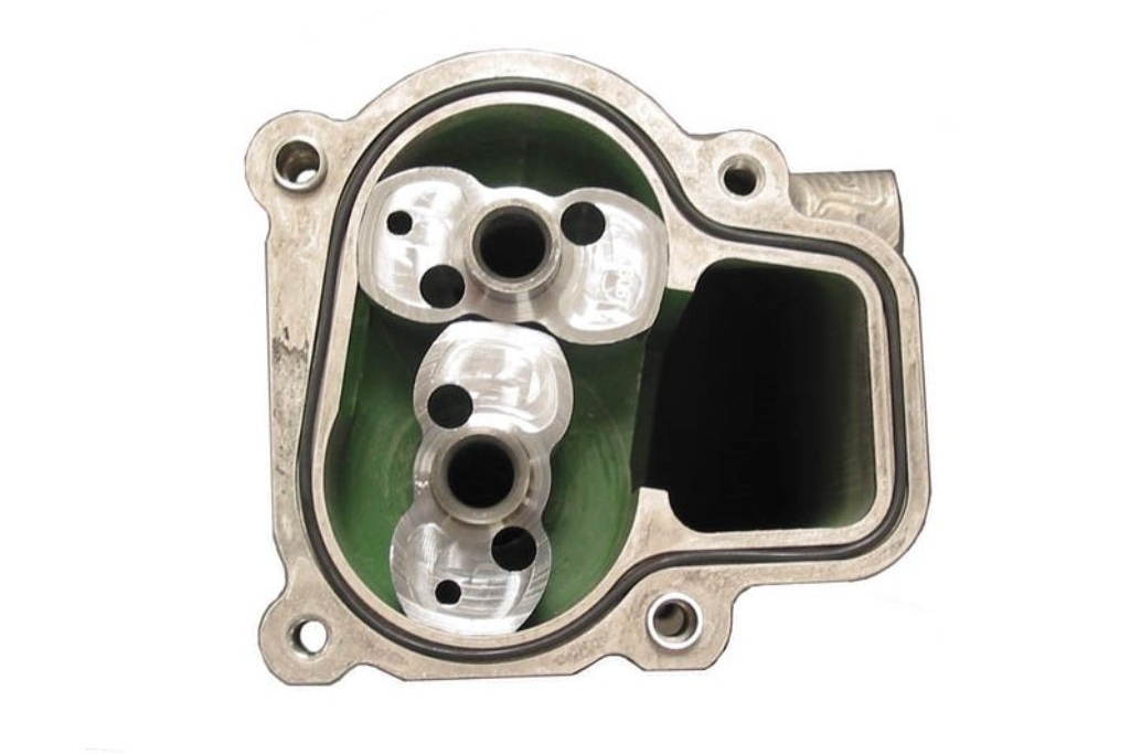
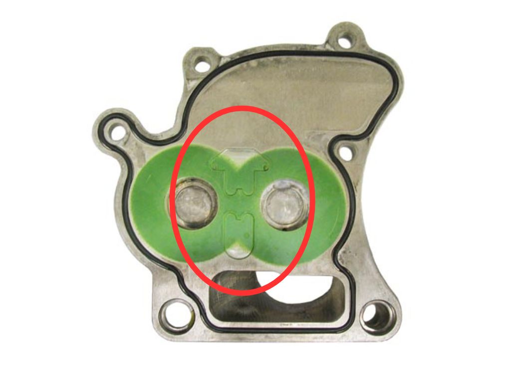
In a pneumatic valve spring air or nitrogen is fed into drillings in the cylinder head at a regulated pressure of (typically between 10 and 20 bar, depending on several parameters such as the volume of the body and the mass of the valve) from a supply bottle mounted externally on the chassis or from a compressor, and then introduced into the pneumatic valve body through a non-return valve.
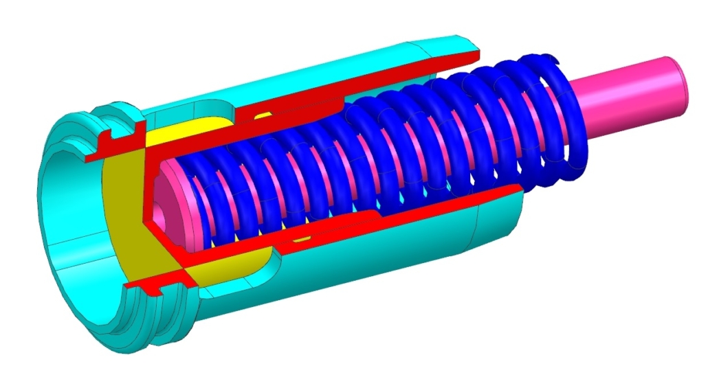
Inside the body, the gas will be compressed to more than 80 bar as it is squashed by movement of a disc secured to the valve with cotters, called the reciprocating seal carrier. Around the outside of this carrier is a seal that runs inside a honed bore inside the body (sometimes the bore is in a separate sleeve that is inserted into the body). At the base of the body is another seal carrier which houses the stem seal.
Both seals are usually energised by a combination of the internal gas pressures in the body and metal garter springs which forces the seals out even when there are lower gas pressures present.
The exact construction and materials that are used to manufacture the seals remains a closely guarded secret between the seal manufacturers and the engine manufacturers. This is even true on the seals that we supply to customers rebuilding historic Formula 1 engines.
Both the reciprocating seal and the stem seal will be required to maintain a perfect seal whilst running at phenomenal speeds. It is imperative that the surfaces aren’t dry, otherwise the seals will overheat. The running surfaces of both seals have to be lubricated with oil, but the introduction of oil has to be carefully controlled.
Thankfully, in the environment that the pneumatic valve springs find themselves in, there is plenty of oil around. In the valvetrain chest, which is the space around the pneumatic valve bodies, there is always a mist of oil present. This oil finds it way onto the walls of the bores in each body, and can then lubricate the reciprocating seal.
The reciprocating seal has a shallow groove running around the middle that fills with oil, and when the seal moves the pressure in the groove increases until it reaches a point where the oil is forced into the body. Once in the body, the oil can then lubricate the static stem seal.
But too much oil in the body can be catastrophic. Unlike gas, oil is virtually incompressible. If too much oil gets into the body of a pneumatic valve spring then it will hydraulically ‘lock up’. This in turn results in massive forces on the seals and carriers, which can lead to catastrophic engine failure.
The amount of oil present can be maintained by using small pressure relief valves (PRV), which will open when too much oil is present, and if located correctly they will vent the oil out of the body. The operation of these valves is similar to the much larger PRV that are found next to the oil pressure pump.
Normally each pneumatic valve body will contain its own miniaturised PRV. The PRV consists of a tiny ball bearing which is pressed by a spring against a conical face to seal off the oilway. When the pressure in the body reaches a certain level the spring force is overcome and the ball moves, opening up the oilway. The installed length of the spring is carefully preset with a graded-length screw, which is selected during build to ensure that the PRV opens at the right pressure.
So, when the amount of oil present in the body gets too much, the pressure in the body opens up the PRV and the oil escapes out. However, it’s not always as simple as this. Sometimes gas will escape with the oil, depleting gas from the body, and so more gas will be required. Effectively, the body has to take a gulp of gas from the supply source.
If this occurs repeatedly or if the seals start to leak then the gas bottle will soon be exhausted and will have to be topped up, which brings us back to the lengthy pit stop, frustrated driver and exacerbated mechanic.
Normally this leakage doesn’t just go away, and if there isn’t enough replacement gas added during the pit stop then eventually the bottle will run out. In Formula 1 the emphasis is on saving engines for future use, so the team will normally elect to retire the car rather than risk a loss of valve control and ultimately engine failure.
Pressure Regulator
One important component in the pneumatic valvetrain is the pressure regulator. This device is spring-loaded and can be set to ensure that the supply of the gas going into the engine is at a consistent pressure regardless of the pressure of gas in the bottle.
The pressure regulator on a race car is a more complicated version of one that might be found on a diving bottle. It’s normally mounted in a cavity in the sidepod, and as such is subjected to extreme vibrations and temperatures.
This regulator also typically has two pressure sensors installed – one will read the pressure from the bottle, and the other will record the pressure going into the engine. A deteriorating bottle pressure is a sure sign that the engine is consuming gas.
The Benefits of Pneumatic Valve Springs
Thanks to its ability to be able to cope with higher loads, a pneumatic valve spring offers two significant benefits over a wire spring. First of all, most wire sprung engines are limited to around 12,000 rpm because of the strength of the springs. If you want to go past that speed then you’ll probably have to switch to a pneumatic valve spring.
Secondly, most race engine designers want a profile that will give rapid opening of the valve, followed by the required duration of opening and then a rapid closing of the valve. Again, wire springs can be a limiting factor for the aggressiveness of the cam profile. If you want to run aggressive cam profiles then you’ll probably benefit from a pneumatic valve spring.
So how is a pneumatic valve spring superior to a wire spring? An esteemed engineer by the name a of Professor Gordon Blair wrote a series of articles for Race Engine Technology that examined valve springs in great detail.
In one of these articles (“Steel Coils Versus Gas”, RET 23) he included an in-depth comparison between a single-coil steel spring and a nitrogen-filled pneumatic valve spring. He analysed the amount of valve bounce from both systems and surmised that the valve control with a pneumatic spring was superior to that provided by the steel spring.
He highlighted several reasons for this improvement in valve control. First, the mass of the reciprocating seal and carrier was only around one-fifth of that of the steel spring. Also, the gas spring displays an inherent damping behaviour thanks to the hysteresis of the gas. And perhaps most important, unlike helical wire springs, pneumatic valve springs cannot suffer from surge problems.
Will We See Pneumatic Valve Springs on the Road?
The simple answer to this question is no. For a start, most road engines don’t need to run at the speeds seen in Formula 1. Moreover, most road engines don’t need to use aggressive cam profiles. So a conventional wire compression spring can do the job and there are plenty of metallurgical advances that make a wire spring incredibly robust.
The other problem is that, despite 30 years of research, pneumatic valve springs are still relatively unreliable, certainly when compared to a wire spring. There is an incredible amount of care and attention that is required when assembling a pneumatic valve spring. Just the slightest amount of dirt or debris can cause the seals to leak. In the OEM world of mass-production, it would be extremely difficult to assemble pneumatic valve springs on a production line within a sterile environment.
So it’s highly unlikely that you’ll ever see a warning sign flash up on your dashboard whilst you’re driving to the shops telling you that you need to come in for an unscheduled pit stop for a bottle top up.
Modatek can supply parts and consultancy to customers who want to rebuild the pneumatic valve springs in their historic engines. Get in touch to find out how we can help.
https://modatek.co.uk/wp-content/uploads/2024/07/AVS-Assy-2.jpg7681024Matthew Granthttps://modatek.co.uk/wp-content/uploads/2024/02/Modatek-Logo-V3-Logo-for-Header-2-300x137.jpgMatthew Grant2026-03-16 10:21:212026-03-18 10:22:05PNEUMATIC VALVE SPRING SECRETS REVEALED
In our recent email newsletter we looked at the latest controversy to grip Formula 1, which is the subject of compression ratio. We were deluged with enquiries from people who had missed out on this newsletter, so we decided to republish it here. (If you haven’t already subscribed to our weekly email newsletter then you’re missing out!)
(Photo copyright: Pathompong Thongsan from Dreamstime. Before you ask, this is most definitely NOT an image of the inside of a Formula 1 engine )
The 2026 Formula 1 technical regulations are the most heavily prescribed set of rules in the history of Formula 1 (writes Modatek’s Matt Grant). As an example, 40 years ago the rules that defined the engine barely covered half a page. Conversely, the rules for the 2026 Formula 1 powertrain are over 70 pages long.
Nevertheless, every engine manufacturer will be doing their upmost best to find hidden loopholes in the rules. And the recent news that two manufacturers (Mercedes HPP and Red Bull Powertrains) might have been able to exploit some poorly-defined wording in the rules comes as no surprise.
Rival manufacturers are claiming that both companies have found a way to increase the compression ratio when the engine is running. At the heart of this controversy is article C5.4.3, which states: “No cylinder of the engine may have a geometric compression ratio higher than 16.0. The procedure to measure this value will be detailed by each PU Manufacturer according to the Guidance Document FIA-F1-DOC-C042 and executed at ambient temperature. This procedure must be approved by the FIA Technical Department and included in the PU Manufacturer homologation dossier.”
(Incidentally, the first clue that the FIA might have not properly thought about this rule is their inaccurate definition of the compression ratio number. 16.0 on it’s own is meaningless, it has to be relative to another number, so one has to assume that they mean 16.0:1)
Rival manufacturers have claimed that both Mercedes and Red Bull have found a way to increase the compression ratio to around 18.0:1 when the engine is running. They point to another regulation, article C1.5, which is a long-standing rule that says: “Formula 1 Cars must comply with these regulations in their entirety at all times during a Competition.”
The argument they make is that whilst the engine might be legal when it is measured at ambient temperature, it breaches article C5.4.3 when it is running on the track, and there is no way to measure compression ratio during running.
I’ve been asked by a number of people about this, so here are my thoughts. I should point out that I don’t have any insider information, and as Baz Lurhmann once wrote, “my advice has no basis more reliable than my own meandering experience,” so feel free to ignore this.
Personally, I think the FIA were already aware that engine manufacturers were actively trying to increase the compression ratio during running, which is why they decided to drop the limit from 18.0:1 in 2025 to 16.0:1 this year. They probably reasoned that this allowed sufficient headroom to ensure that nobody exceeded the previous limit of 18.0:1 when the engines are running.
But the question everyone is asking is just how are Mercedes and Red Bull able to increase the compression ratio during running? Do they have some clever trick bit of kit that can circumvent the rules?
In actual fact, I think manufacturers have been able to increase the compression ratio during running for years, often inadvertently. The compression ratio is defined as the ratio of the the maximum cylinder volume (when the piston is at bottom dead center, BDC) to the minimum cylinder volume (when the piston is at top dead center, TDC). So if the volume of the combustion chamber at TDC is reduced, then the compression ratio is increased.
One way to reduce the volume at TDC is to increase the length of the connecting rod, which happens naturally on every engine, and which explains why I think everyone has been doing this for years. On Formula 1 engines that I have worked on, at maximum engine speed the rod stretches by around 0.2mm due to the inertial load from the piston, so there is an inherent increase in compression ratio, whether you want it or not.
There is talk by some that Mercedes and Red Bull are reaching 18.0:1, which would equate to a rod stretch of around 0.5mm. I wouldn’t be surprised to find out that they have cleverly designed the rod to expand in length due to a combination of the piston inertial load and thermal expansion. This would almost certainly be legal, as there is no regulation about the longitudinal stiffness or thermal expansion coefficient of the connecting rod.
Like I said though, these are just the ramblings of an ex-Formula 1 engine designer, with no factual evidence. But I’d love to hear your thoughts on this controversy. How do you think they’ve been able to raise the compression ratio during running? Is it even a controversy, if everyone has been doing it for years anyway? And is this just a distraction from other loopholes that we’re all missing?
https://modatek.co.uk/wp-content/uploads/2026/02/dreamstimemaximum_151303247-Copy.jpg12962304Matthew Granthttps://modatek.co.uk/wp-content/uploads/2024/02/Modatek-Logo-V3-Logo-for-Header-2-300x137.jpgMatthew Grant2026-02-02 17:02:042026-02-02 17:04:05F1 COMPRESSION RATIO CONTROVERSY
Whilst the article covered the fundamentals, it missed one crucial dimension: the actual video footage captured inside a running engine.
This technology is nothing short of revolutionary. It enables engineers visually track valve and piston motion, combustion dynamics, and gas behaviour in real time. Even more remarkable is that it detects temperature shifts and operating conditions with unmatched precision. For a visually driven field like engine development, this capability transforms how we understand and optimize performance.
To illustrate the power of this imaging, Professor Jon Lesko compiled four examples from a 1.6-L I4 GTDI engine that showcase the depth of insight thermal imaging can provide.
Flame Propagation and Kernel Growth
Flame kernel development is highly sensitive to the orientation of the spark plug’s ground strap. For optimal combustion performance, the strap must be positioned to minimize interference with the dominant in-cylinder charge motion; a factor especially critical in GTDI (Gasoline Turbocharged Direct Injection) engine designs. Since charge motion is shaped by the geometry and features of the combustion chamber, strap alignment must be customized for each engine configuration. This detail directly influences idle stability and throttle tip-out behaviour, where early-stage combustion plays a pivotal role in overall efficiency and emissions control.
In this particular study, cylinder one is viewed from the front, with the ground strap oriented toward the exhaust valve. The charge motion flows left to right, sweeping toward the exhaust valve. The engine operates at 2,840 RPM, 6 bar BMEP (56 lb-ft), and λ = 1—conditions that represent near-ideal combustion. Using crank-angle-resolved imaging, the video sequence captures flame kernel formation in one-degree increments up to 10° after ignition. Each crank angle is 30 samples, offering a detailed visualization of early flame growth. For comprehensive analysis, formal datasets include 300 frames per strap orientation and operating point.
These imaging datasets serve dual purposes: guiding the design of combustion systems and validating computational fluid dynamics (CFD) models. Today’s advanced simulations incorporate not only spark plug type but also ground strap orientation, which is increasingly treated as a tunable design variable in high-performance applications.
720° Rotation – Front View
At 5,000 RPM and 5 bar BMEP (47 lb-ft), a complete engine cycle of the 1.6-litre inline-four GTDI engine is captured from the front, offering a detailed thermal perspective of in-cylinder dynamics. Prominently featured in the frame is the blackbody probe, precisely positioned just left of the spark plug’s negative electrode. This probe plays a critical role in validating benchtop calibrations across multiple wavelengths, helping confirm the absorption and emission profiles of in-cylinder gases and fuels. Its temperature, influenced by combustion gases, is finely tuned by adjusting its thermal conduction path to the cylinder head. These probes are used exclusively during validation and can be inserted either manually or via automated systems.
The sequence begins with the piston moving downward and out of view, exposing the bore wall. As the intake valves open, the injector fires into the chamber, briefly obscuring both the spark plug and the blackbody probe. Injection concludes just before the intake valves reach full lift. As the cycle progresses, the intake valves rotate out of the camera’s field of view.
With the valves closed, the piston ascends toward top dead centre (TDC). Through a narrow-band 3.9 µm infrared filter, early combustion becomes faintly visible, even though many combustion byproducts remain optically transparent. As ignition intensifies, swirling gases and particulates fill the chamber, gradually dissipating as the air-fuel mixture is consumed.
The exhaust valves then begin to open, glowing brightly due to the selected integration time and display settings. At this operating point, the valves exhibit minimal rotation, a behavior not uncommon under certain load and speed conditions. As the exhaust phase concludes and the valves close, the piston completes its upward stroke, marking the end of the full 720° engine cycle.
Valve Rotation – A Design Imperative
Looking up from the top of the bore wall you can see the complete rotation of the exhaust valve after roughly 950 engine cycles. The engine is operating at 5,000 RPM and 14-bar BMEP (131 lb-ft). Over this sequence, the valve steadily heats, with rising radiance marking the temperature increase. At this condition, the exhaust valve, measured from the front of the engine, reached a peak of 851 °C at the stem-to-fillet transition. The spark plug’s negative electrode tip was even hotter, at 968 °C.
Valve rotation patterns vary by engine; some valves start from different positions or even reverse direction during operation. Designers manage these dynamics to ensure rotation occurs at speeds consistent with steady-state operation. Despite the higher speed and load, particulate output from the exhaust port did not rise significantly, showing that most particulates were consumed during combustion.
720° Rotation – Bore Wall Perspective
Captured from above the bore wall of a 1.6-L I4 GTDI engine operating at 5,000 RPM and 5 bar BMEP (47 lb-ft), this sequence offers a full-cycle thermal view from inside the combustion chamber. Prominently featured is the blackbody probe, positioned just left of the spark plug’s negative electrode. This probe serves as a calibration reference across multiple wavelengths, helping validate the absorption and emission profiles of gases and fuels. Its temperature, influenced by combustion gases, is regulated by adjusting its thermal conduction path to the cylinder head. These probes are used exclusively during validation and may be inserted manually or automatically.
The piston crown, shaped to match GTDI design principles, begins the cycle by descending out of view, exposing the bore wall. As the intake valves open, fuel injection initiates, briefly obscuring both the spark plug and the blackbody probe. Injection concludes just before the valves reach full lift, and the intake valves gradually rotate out of the camera’s field of view.
With the valves closed, the piston ascends toward top dead centre (TDC). Through a narrow-band 3.9 µm infrared filter, early combustion becomes faintly visible, despite the transparency of most combustion byproducts. As ignition intensifies, swirling gases and particulates fill the chamber, gradually dissipating as the mixture is consumed.
The exhaust valves then begin to open, glowing brightly due to the selected integration time and display settings. At this operating point, valve rotation is minimal, a behaviour occasionally observed under similar speed and load conditions. As the exhaust phase concludes and the valves close, the piston completes its upward stroke, marking the end of the full 720° engine cycle.
Future Potential: AI and Automation
Jon Lesko and his team have pioneered this imaging technology, but the next leap lies in automation. Historically, operators required extensive training to use these systems effectively. Lesko’s protocols, developed over decades, are now ripe for AI integration.
“I’ve designed a miniaturised, multi-wavelength solid-state imaging system that could be semi-autonomous,” Lesko explains. “The software I built in the late ’90s was essentially machine learning. Today’s AI can automate both acquisition and analysis, delivering near real-time data.”
This opens doors for collaboration with universities or elite motorsport teams. With accurate chamber-level data, engineers can push engines closer to their true limits—no longer constrained by the weakest link.
With proper funding, updated hardware and AI-driven software could make this a user-friendly, high-impact tool for engine development.
For further information contact:
Jon Lesko Infrared Detection & Analysis Systems Email: jonmlesko@gmail.com Phone 001 (303) 808-4837
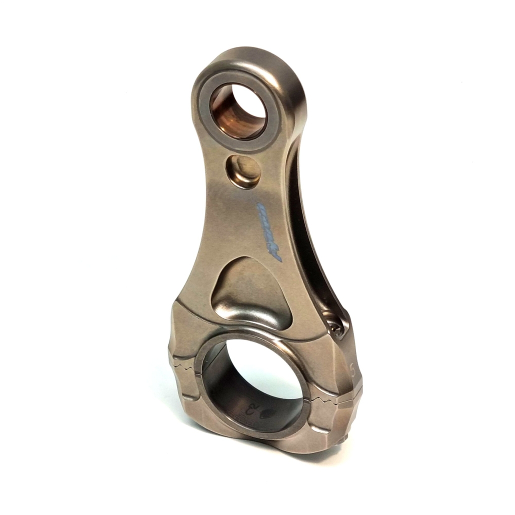
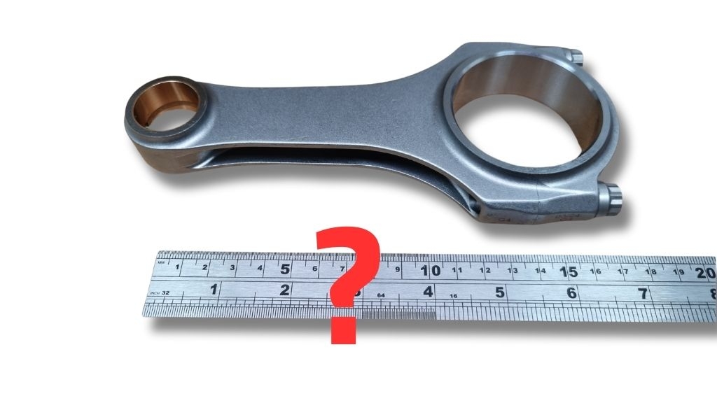
Are H-section con rods any good? There seems to be a lot of false information on various social media channels. We take a look at why you shouldn’t trust everything you read on the internet, and offer our opinion on this much-maligned engine component.
The comment caught our attention, mainly because it was completely untrue:
(An H-section or H-beam rod resembles the letter H when looking down the rod with the journal axis horizontal, whereas an I-section rod looks like the letter I. To put it another way, an H-section rod has the lightening pockets on the sides, and an I section rod has the lightening pockets on the front and rear.)
The comment was accompanied by a photo of a bent con rod attached to a cracked piston. I did a Google reverse image search, and I discovered that the first use of this image didn’t attribute the failure to the con rod design (it was probably caused due to a hydraulic event). But someone else then used this photo and claimed that the failure was because the con rod was H-section. Then another armchair expert claimed that “all H-section rods are made in China”, and the myth has then snowballed across the internet.
Now, as far as debates go, this one is probably not that important in the grand scheme of things, but I thought it was interesting to see how some people can latch on to untruths on the internet, and then profess to know everything there is about, in this case, con rod design.
In my experience, I’ve not seen any evidence to say that all H-section rods are bad, or that they are infinitely inferior to I-section rods. A great number of engines that I have worked on have used H-section rods, and with no failures that can be traced back to the con rod design. In fact, some designs, like the Cosworth CA Formula 1 con rod, transition between the H-and I-style designs along its length to provide optimal weight reduction and distribution.
But some might say that I’m going to biased, given that we sell H-section rods, so I thought it might be handy to refer to an in-depth article in Race Engine Technology issue 75, written by David Cooper. Here’s what the article has to say about con rod sections:
“The most obvious variation in con rod design is in the cross-sectional shape used for the main beam section. While a wide range of possible section shapes are available, and can be used – including solid sections of various geometry – the current preferred choice is between either H-beam or I-beam sectional shapes, with virtually all manufacturers queried on the topic for this article supplying either or both types.
“Both can be engineered to provide sufficient strength and stiffness for virtually any application, although neither shape lends itself particularly to higher load applications, for example, than the other.
“Instead it is a case of optimising the chosen section to match the end use. For example, an I-beam rod may have a slightly lower weight for similar stiffness in some applications, whereas an H-beam rod will typically be narrower for a similar stiffness, especially if arranging the rod onto the crankshaft is a significant concern, as in a single-cylinder engine where crank cheeks are close together.
“Ultimately though, comparable performance is achievable with both designs, and the devil is really in the particular design details, the materials used and the manufacturing route/cost requirements.”
The article goes into more detail about the merits of H- and I-section designs, so I won’t reproduce all of it here, but if you do want to learn more then I highly recommend getting hold of a copy.
So there you have it, not everything you read on social media is true. And maybe give H-section rods an easier time next time you see them posted on a company’s social media channels.
We are Cosworth’s official distributor for their historic engine parts, and we supply a wide range of parts for a number of different Cosworth historic engines, from BD, YB and DFV through to the more recent F1 engines like the CK, TJ and CA. Our mission is to help our customers build better engines by supplying high quality parts backed up with a design consultancy that utilises over 25 years experience in top level motorsport.
https://modatek.co.uk/wp-content/uploads/2025/08/H-section-Con-Rods-2.jpg512910Matthew Granthttps://modatek.co.uk/wp-content/uploads/2024/02/Modatek-Logo-V3-Logo-for-Header-2-300x137.jpgMatthew Grant2025-08-19 11:33:322025-08-19 11:58:02H-SECTION CON RODS
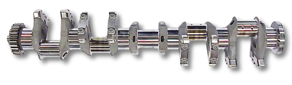
Here is a sneak peek into something that we’ve been developing over the last few years, and we hope it will really help our customers build better engines – this is our very own crankshaft calculator, and it will be available to buy in a few weeks’ time.
To paraphrase the great Keith Duckworth & Mike Costin, I’ve spent most of my career messing about with race engines, and over the years I’ve designed numerous components, including crankshafts (writes Modatek’s Matt Grant).
In fact, Formula 1 V10 cranks were some of the first parts that I designed when I started as an engine designer in the mid-90s. The original design method to determine balancing involved reams of hand calculations and cutting out bits of paper (I kid you not!) to come up with the shapes of the counterweights.
Of course, technology has moved on a lot in the last 25 years. Today we have CAD and Microsoft Excel, and I’ve been designing crankshafts for our customers with our own software that combines CAD models and Excel spreadsheets.
These powerful spreadsheets that not only balance the crankshaft, but also calculate bearing loads, creating plots like the one below for an I4 engine with the gas loading included:
Furthermore, I’ve also created an even more complex spreadsheet that works out the first mode torsional natural frequency and the amplitudes for each order and half order. This is the predicted amplitude displacement for the I4 engine:
All of the calculations are performed in real time, there is no need for FE mesh models to be created or for complex simulations to be run.
Over the last couple of years I’ve been busy combining the balancing, bearing loads and torsional spreadsheets into one mega spreadsheet, and it’s currently being rolled out to a small number of customers. So far the feedback has been extremely positive, one customer even remarked how this is going to change the game of crank design!
So How Does It Work?
I guess that most software vendors would be very reluctant to explain exactly how their programs work, but I’ve taken the opposite view. Everything in my crankshaft calculator is based on tried and tested mathematical processes and formulae, and I’ve even written about it in Race Engine Technology.
For example, the torsional vibration calculations are based on the work done by Holzer, which in turn used equations inspired by Ker Wilson to calculate the stiffness of each section of the crankshaft.
If you want to find our more details, you can still purchase back copies of the two Race Engine Technology publications that featured these articles here:
If you’d like more details about the crankshaft calculator or you would like to register your interest in purchasing a copy then just get in touch via our “Contact Us” page.
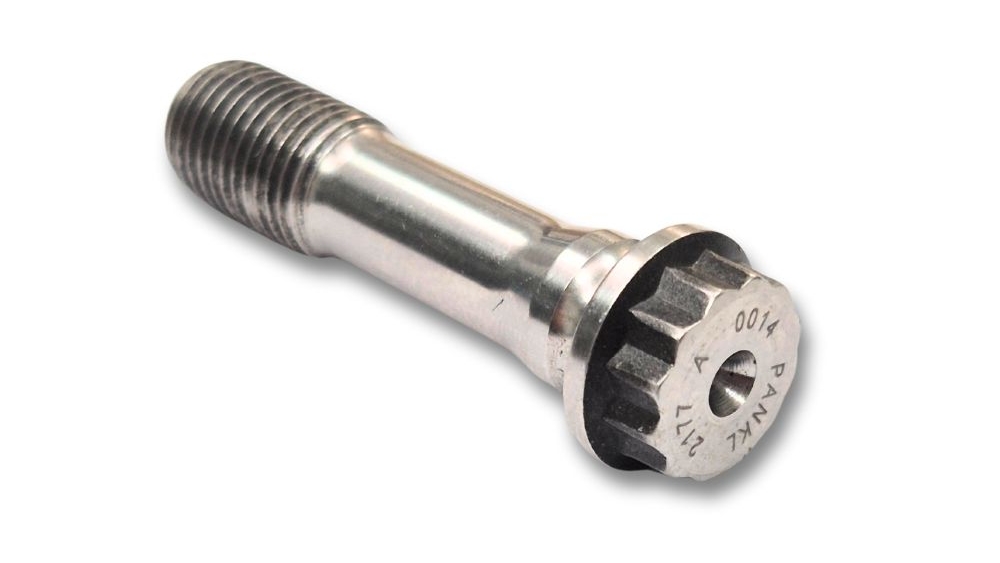
If someone asked you what the most complicated part in a Formula 1 engine is, you probably wouldn’t instantly think of the connecting rod bolt. But this humble-looking fastener is in fact incredibly complex.
When I started as an engine designer at Cosworth way back in the mid-1990s, one of the first parts that I got to design was the con rod bolt for the VJ Formula 1 engine.
On the face of it, this might seem like just another fastener, albeit one that is highly loaded. But I was told in no uncertain terms that this is no ordinary bolt. In fact, I remember being told to add the words “THIS IS THE MOST IMPORTANT PART OF THE ENGINE” to the drawing.
As a measure of just how complicated the con rod bolt for an F1 engine was, the size of drawing ended up being A1 (eight times the area of an A4 drawing), which seems like a lot of space for a part that is less than 2 inches long. But over half of the drawing was devoted to long lists of instructions that detailed how the bolt was to be forged, machined, finished, inspected and handled.
All of this care and attention was necessary because these rod bolts were the only components that were stopping the piston from being ejected upwards every time it reached TDC. In an F1 engine that was revving to 20,000 rpm (which is what the Cosworth CA could reach in 2006), that was over 300 times per second.
In addition to this insane frequency, the loading on the rod bolt was huge. At 20,000 rpm the piston has a deceleration of over 10,000 G. Even for a 250g piston, that’s equivalent to it weighing 2.5 metric tons – that’s like hanging a Range Rover from just two rod bolts!
(This was the best image that AI could generate. I think our jobs are safe for now.)
So to make the bolt as strong as possible, there were loads of steps that had to be carried out. First of all, the material was the best multiphase steel alloy that was available at the time. The head of the bolt was then forged, giving the optimum grain flow.
The downside to the specialist material and the need for forging was the lead time. It could take as long as 9 months to produce the bolts, which often meant that the rod bolt was one of the first components to be designed, before even the cylinder block and heads were started.
Secondly, the threads ended up being a custom size. The radius in the roots of the threads was meticulously defined by an international standard, so the actual thread naming convention was MJ9x1.0 4h-6h to BS6293 Parts 1 & 2, to be exact.
The pitch in the corresponding threads in the con rod weren’t the same as the pitch of the bolt thread. It was deliberately ‘depitched’, so that when the threads in the rod were stretched under load they would match up with the shape of the threads on the bolt. This in turn helped to even out the stresses in all of the threads.
There was also additional instructions to make sure that the shank of the bolt was as smooth as possible and free from any scratches, which might otherwise act as a stress razor. Later bolts, like the ones from the TJ engine, were superfinished to give them a mirror-like finish.
On top of that, there were incredibly tight geometric and dimensional (GD&T) tolerances that ensured that the face of the bolt was as perpendicular as possible to the bolt axis and thread (the maximum allowable runout was just 76 microns).
So all in all, the Formula 1 con rod bolt ended up being one of the most complicated parts in the entire engine.
We are Cosworth’s official distributor for their historic engine parts, and we supply a wide range of parts for a number of different Cosworth historic engines, from BD, YB and DFV through to the more recent F1 engines like the CK, TJ and CA. Our mission is to help our customers build better engines by supplying high quality parts backed up with a design consultancy that utilises over 25 years experience in top level motorsport.
https://modatek.co.uk/wp-content/uploads/2025/06/MTK0080-TJ-Con-Rod-Bolt-1-edited.jpg5631000Matthew Granthttps://modatek.co.uk/wp-content/uploads/2024/02/Modatek-Logo-V3-Logo-for-Header-2-300x137.jpgMatthew Grant2025-06-03 15:07:592025-06-03 15:10:29FORMULA 1 CON ROD BOLT TECH
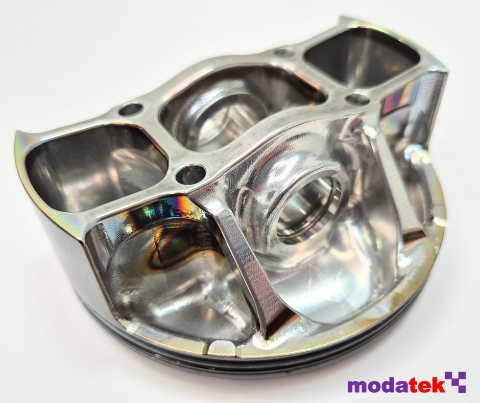
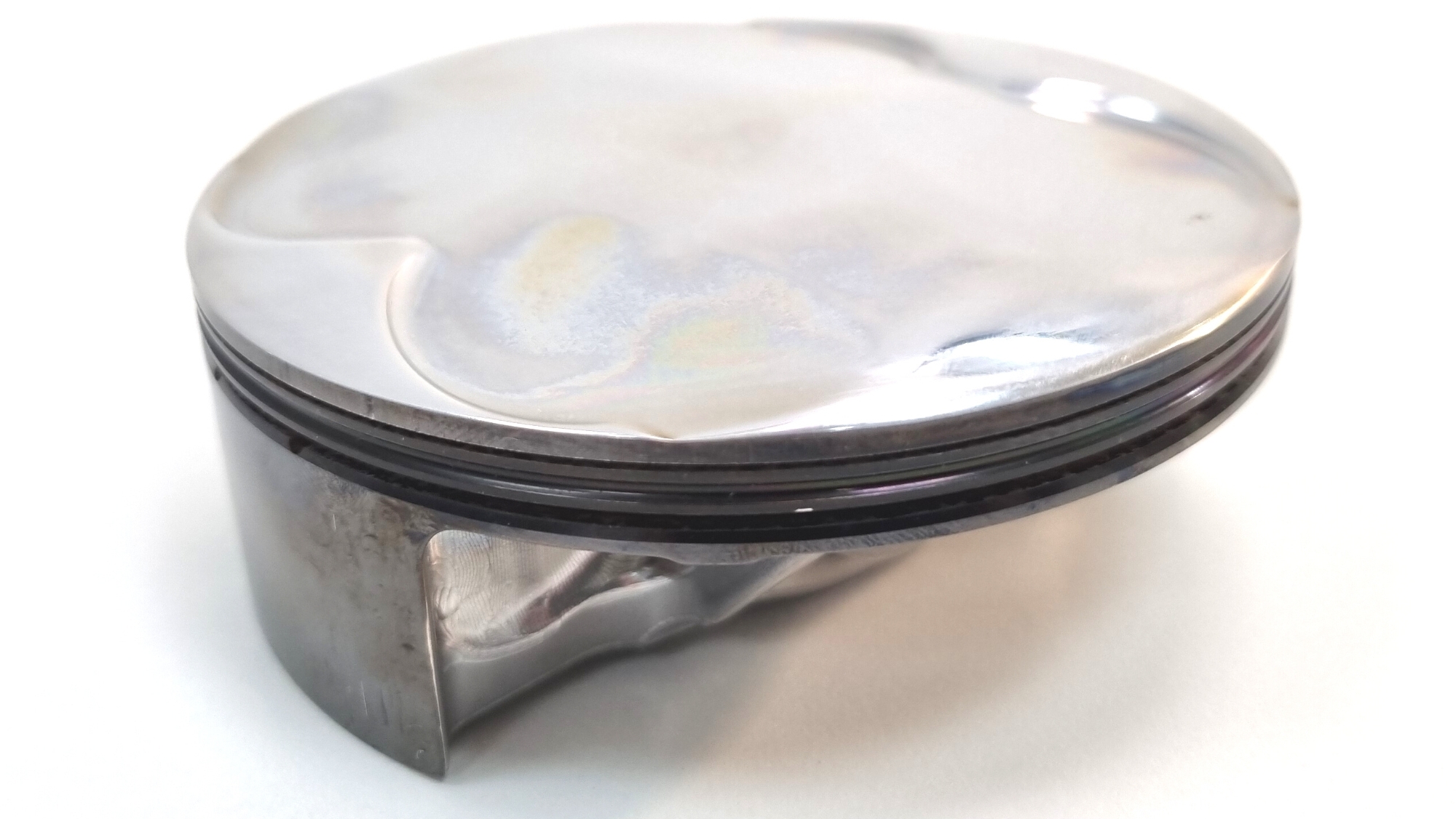
There’s more to a Formula 1 piston than first meets the eye. The last of the V8 naturally aspirated engines from 2013 were built with pistons that contained lots of technical secrets. Let’s take a closer look at what some people call an engineering work of art – the Cosworth CA2010 Formula 1 piston.
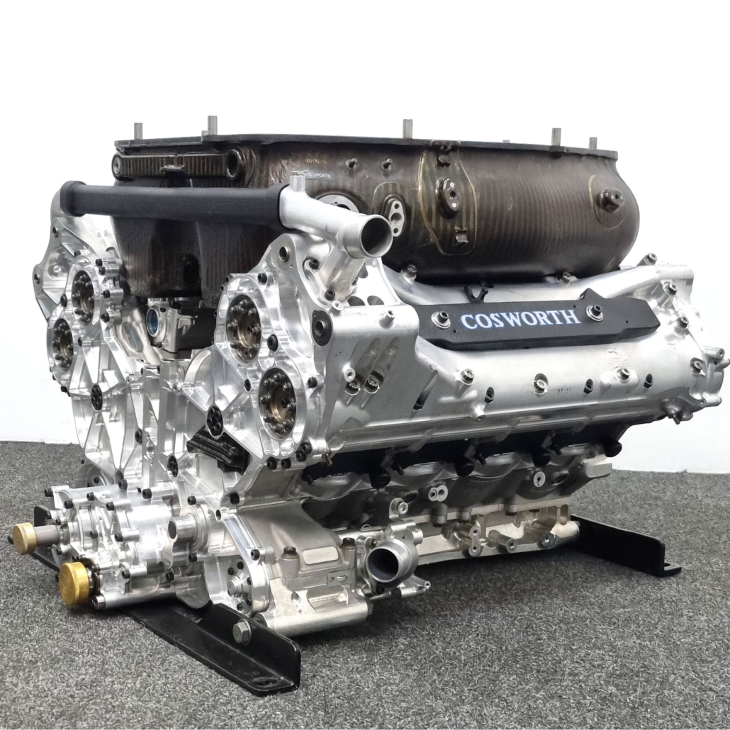
The Cosworth CA2010 engine was a development of the CA, an engine which was designed and built for the 2006 season for use by Williams. As there were no restrictions on engine speed back then, peak speed was pushed to the limit and the CA was capable of reaching 20,000 rpm, making it the fastest engine on the grid.
Sadly Cosworth were forced out of Formula 1 at the end of 2006, but four years later were back with the CA2010, powering Williams again alongside the three new teams, Virgin Racing, Lotus Racing and Hispania Racing. By now the rules mandated a maximum speed of 18,000 rpm, but engine life had increased almost threefold, so there was no let up in the pursuit of reliability.
Formula 1 Piston Mass
One of the most stressed parts in the engine was the piston, and it’s not hard to see why. At a speed of 20,000 rpm the piston was subjected to accelerations of over 10,000 G (that’s not a typo, that’s ten thousand G!). If you paid attention to your high school physics lessons then you’ll remember that force is mass multiplied by acceleration, so reducing piston mass was a critical step to reducing the forces that the piston was exposed to.
The piston design represented the culmination of years of hard work to reduce mass, and the CA2010 piston hit the scales at just 215 g. Considering that the material had to be an aluminium alloy as mandated by the F1 technical regulations, this was a remarkable achievement.
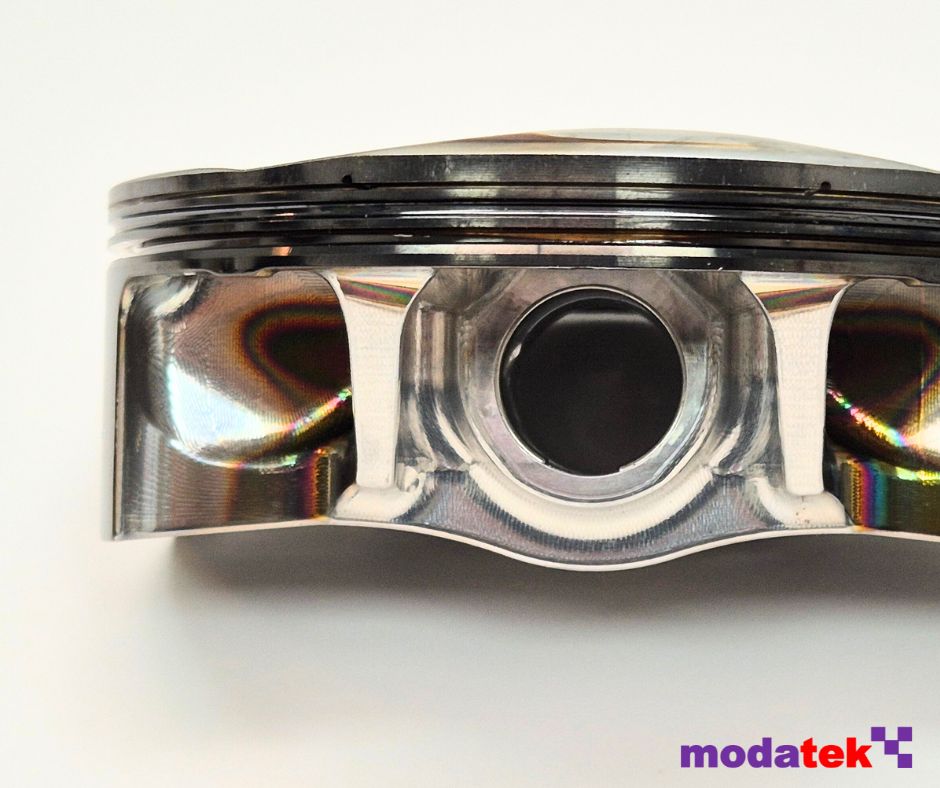
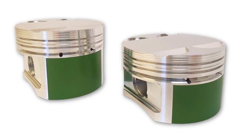
Undercrown Shape
A lot of the weight saving came from the unique shape of the piston. Alex Hitzinger, who was the chief engineer in charge of the design of the CA engine, recently commented on how the undercrown shape of the piston evolved. “We came up with this design philosophy (dog bone shapes, extremely stiff, hollow structures) through a design study we did for a very thin walled investment cast titanium piston. We never made one, because titanium got banned as a piston material before we could try it, but we learned a lot through that exercise and the result was the a piston that was capable of revving to 20,000 rpm.”
Looking at the undercrown, the shape looked like a fairly conventional boxed and bridged design. However, there were a number of clever design features that were optimised through an extensive period of FEA (finite element analysis).
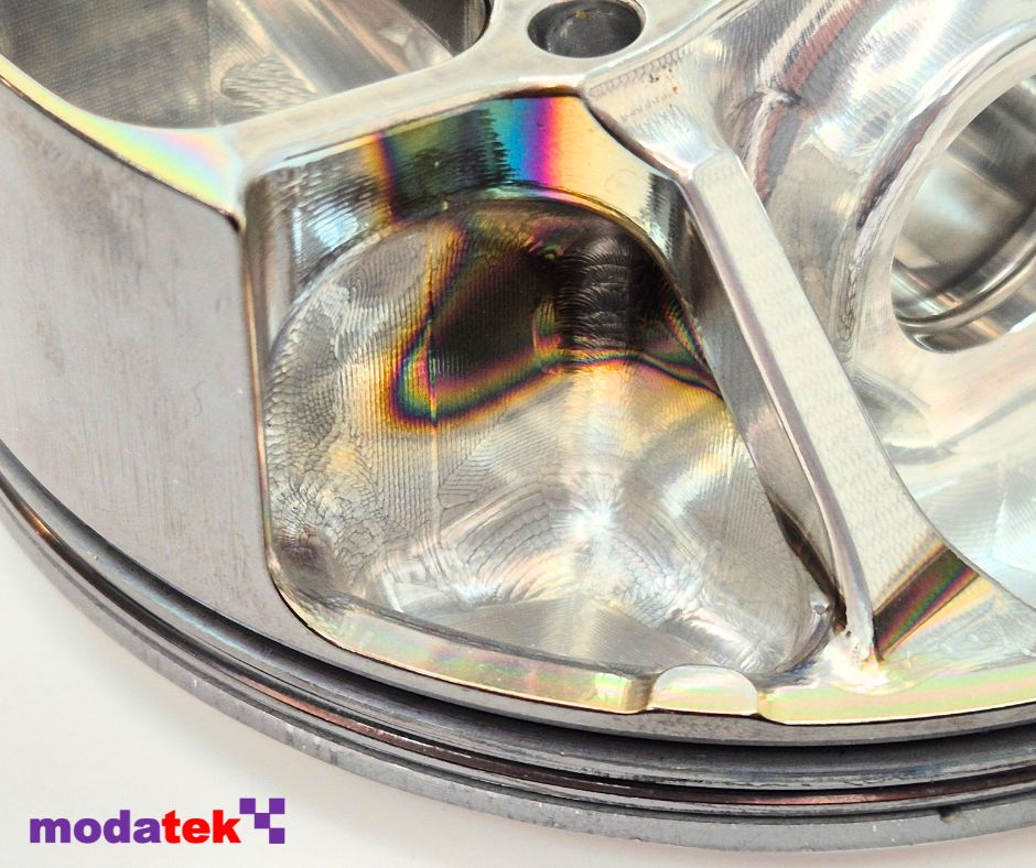
One of these features was the vertical drillings at each corner of the central box section that carried the pin bores. These drillings were actually slightly angled inwards, and were there purely for mass reduction.
The area underneath the buttresses was waisted down, and there was no material underneath the spars of the box section. These features couldn’t be generated from forging and so have had to be machined out. In fact, the entire undercrown had to be extensively machined to remove any surface defects that might have been left over from the forging process.
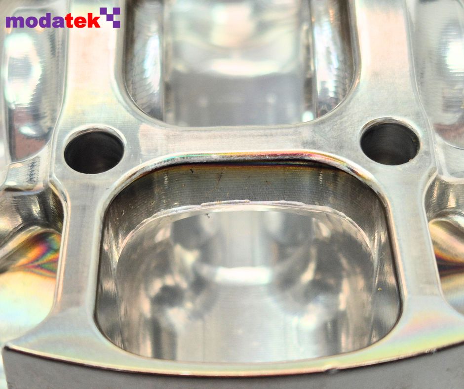
Crown Shape
The design of the crown was carefully shaped to match the corresponding geometry of the combustion chamber in the cylinder head. The crown shape consisted of a diamond-shaped central flat section which actually wasn’t flat. Although difficult to see in photos, the crown of the piston was very slightly domed, which at TDC created a small flat bowl into which the spark plug would initiate the combustion of the air and fuel mixture.
The crown included a pair of very shallow pockets for clearance to the inlet valves and another pair for the exhaust valves. Any sharp edges had to be carefully blended away to reduce the chances of pre-ignition.
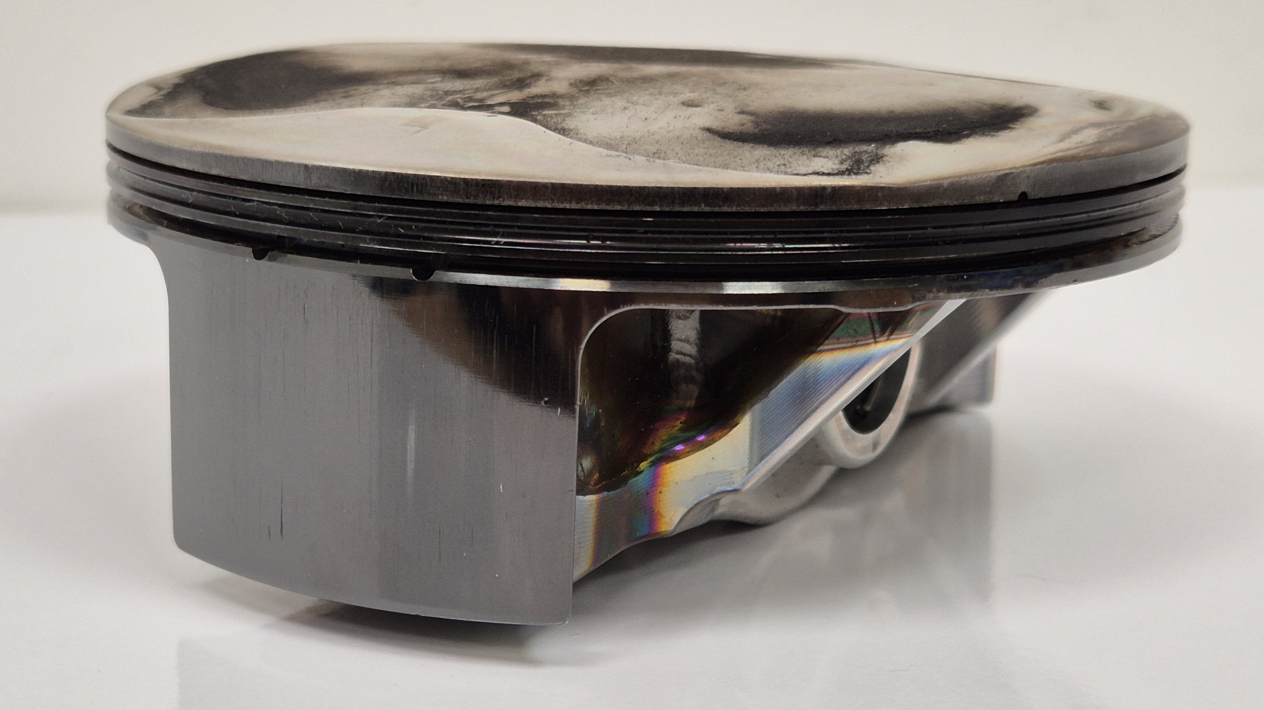
One of the obstacles that had to be overcome was stopping the crown from melting, hence each piston was cooled by six oil squirt jets. The contact with hot oil resulted in the staining that could be seen on the undercrown after extended periods of running.
Ring Grooves
One of the most notable features of the piston was the tight packaging of the ring grooves, which were moved upwards as much as possible. Like most F1 pistons of this era, the sealing of the cylinder bore wall was accomplished with just one compression ring along with an oil control ring.
The height of the compression ring groove was incredibly small at just over 0.63mm. Inside this groove were small horizontal ports that fed combustion gas into the back of the groove and thus helped force the ring out towards the bore.
Likewise, the oil control ring groove was also very narrow at 1.5 mm height, and it contained ports that allowed oil to drain from within the groove to the underside of the piston. Between the two ring grooves was what’s known as an accumulator groove. This was a vee shaped groove that created a volume of gas below the compression ring. This then helped to maintain the differential pressure across the ring that was required for effective sealing.
Skirt
The skirt of the piston was very short, just enough to minimise rocking of the piston in the bore. The coating on the skirt was DLC (diamond like carbon), which had been introduced in 2004 on the forerunner to the CA engine, the TJ. Cosworth estimated that the coating was worth around 4 bhp on the TJ, thanks to the coating’s ability to reduce friction.
The skirt of the piston was very short, just enough to minimise rocking of the piston in the bore. The coating on the skirt was DLC (diamond like carbon), which had been introduced in 2004 on the forerunner to the CA engine, the TJ. Cosworth estimated that the coating was worth around 4 bhp on the TJ, thanks to the coating’s ability to reduce friction.
The profile of the skirt was a complex shape that featured both barreling and ovality. This shape had been optimised through FEA and dyno testing to ensure that the skirt matched the shape of the cylinder bore when the piston was distorted from loading and thermal expansion.
We’ve taken some of these details from an excellent article written by Ian Bamsey in Race Engine Technology issue 073. You can purchase a back copy of this publication here.
We are Cosworth’s official distributor for their historic engine parts, and we supply a wide range of parts for a number of different Cosworth historic engines, from BD, YB and DFV through to the more recent F1 engines like the CK, TJ and CA. Our mission is to help our customers build better engines by supplying high quality parts backed up with a design consultancy that utilises over 25 years experience in top level motorsport.
https://modatek.co.uk/wp-content/uploads/2025/04/CA-Piston-1.jpg788940Matthew Granthttps://modatek.co.uk/wp-content/uploads/2024/02/Modatek-Logo-V3-Logo-for-Header-2-300x137.jpgMatthew Grant2025-04-10 14:10:502025-06-03 15:08:56THE HIDDEN SECRETS OF A FORMULA 1 PISTON
Back in July last year, a 1972 McLaren M19 circulated around a very wet Silverstone circuit. This might not seem so remarkable, except for the fact that this represented a significant milestone for the future of historic motorsport. Why? Because the Cosworth DFV engine in the McLaren was being fed with fully synthetic petrol, a sustainable fuel from Zero Petroleum that promises to be the replacement for fossil fuels in the years to come. But what are sustainable fuels and lubricants, and why are they so important?
Sustainable synthetic and bio-synthetic fuels and lubricants could be the solution to the growing need to decarbonise motorsport. They are one of a number of different tactics that we can employ today to reduce carbon emissions. And unlike other methods such as electrification or switching to hydrogen fuels, the use of sustainable fuels and oils requires virtually no modifications to existing IC (internal combustion) engines.
Indeed, as part of the FIA’s desire to become ‘carbon net zero’ by 2030, a number of its top tier categories have already started to mandate the use of these sustainable fuels. WRC switched over to 100% sustainable fuel in 2022, and Formula Two and Formula Three began to ramp up the percentage of sustainable fuel used in their cars in 2023. But perhaps the most noticeable move to sustainable fuel will be when Formula 1 switches over in 2026.
In the world of historic motorsport, the use of these sustainable fuels will become even more necessary if we want to continue to use the existing IC engines that the historic cars are famous for. Who would want to contemplate replacing the iconic Cosworth DFV in the aforementioned McLaren M19 with a battery pack, inverter and electric motor, for example?
A couple of years ago I wrote an article for Race Engine Technology that looked at how these sustainable fuels and lubricants are manufactured (1). Without wanting to sound arrogant, I’ve written dozens of articles for this publication but this was in my mind probably the most important subject that I’d tackled in my 10 years of writing.
There is so much misunderstanding and misinformation in the media today about decarbonising vehicles that I thought it would be interesting to write a blog post about sustainable fuels and lubricants, and with kind permission from Race Engine Technology, I’ve been able to reuse some of the original article.
Why Do We Need Sustainable Fuels & Lubricants?
When it comes to rising carbon levels in the atmosphere, it is usually the IC engine that is maligned and not the fossil fuels themselves.
I spoke with Rebecca Mann of Coryton, who are already supplying sustainable fuel into main stream motorsport. “All too often, we demonise the IC engine,” says Mann, “but it’s the fossil fuels we put in them that cause the environmental problems. And, if we want to look at the actual environmental impact that we are making we really need to look at the bigger picture. The life cycles of the vehicle and fuel runs from its production to its disposal, and the various stages involved in this cycle can also include the creation of pollutants.
“If we want to weigh up what’s best for our planet, we need to explore the environmental impact of all these stages. Making the most of our existing vehicles whilst we develop wider solutions, such as EV, really could make a big difference.
“What’s more, sustainable fuel is ready to hit the ground running using our existing infrastructure. This means we can continue to utilise the existing fleet that we have on roads, along with the existing refuelling infrastructure.”
There are numerous arguments for and against the transition to sustainable fuels and lubricants, but probably one of the biggest advantages lie in the shear volume of IC engines that are in use on today’s roads.
“There are 36 million existing cars on the UK’s roads”, continues Mann, “and only 0.5% of which are currently fully electric. And there are 275 million passenger vehicles in Europe. We would rather be making moves to immediately improve these vehicles, rather than just waiting for the entire fleet to be replaced with electric vehicles or other new technologies.
“According to the UK government’s own statistics, sustainable fuel could reduce emissions by up to 80% compared to fossil fuels. Even a staged introduction could remove 130 million tonnes of carbon dioxide in Europe by 2030 – almost the same amount as 33 coal fired power stations would produce in a year.
“And, given sustainable fuel could be introduced much more rapidly than the transition to all-electric vehicles, we believe this is something we should be looking at very seriously to help tackle the climate emergency, whilst the infrastructure for electrification is put in place.”
But just how are sustainable fuels better for the environment than fossil fuels? “Sustainable fuel works by, effectively, recycling carbon,” answers Mann. “The carbon that a sustainable fuel contains is captured or absorbed from the atmosphere during the production process – for example, the agricultural products absorb carbon dioxide whilst they grow.
“Once it is turned into fuel and burnt, that same carbon is then released back into the atmosphere. Fossil fuel, on the other hand, has held its carbon safe for millions of years. Burning it releases additional carbon dioxide into the atmosphere that was not there before.”
There are two different ways to make sustainable fuels and lubricants. Bio-synthetic fuels and lubricants are processed from organic material, whilst synthetic fuels and lubricants are created by a number of chemical processes that use the existing carbon dioxide in the atmosphere. Both categories have their own advantages and drawbacks, such as cost and difficulty. Some fuel and lubricant manufacturers combine both bio-synthetic and synthetic products, whilst others continue to use fossil fuels or oils that are mixed with these sustainable fuels and lubricants.
What are Biofuels?
Bio-synthetic fuels, sometimes referred to as biofuels, and lubricants are manufactured by processing biomass – biomass is term for an organic material such as crops (like corn, soybeans and sugar cane), algae or microbial culture. These organic materials use photosynthesis to capture the carbon dioxide in the air. Burning bio-synthetic fuels is carbon-neutral, as the carbon dioxide that is produced from combustion is balanced out by the carbon dioxide that is required to produce the fuel.
The ‘first generation’ of bio-synthetic fuels and lubricants used arable land to grow the required biomass. However, the downside to this approach is that an intensive amount of land is required – one study (2) estimated that to meet the USA transportation fuel usage requirement, 25% of the total land used for agriculture in the USA would have to be converted over to fuel production.
Consequently, this production of these first generation bio-synthetic fuels and lubricants competes head on with food production, and as a result is not a viable solution. Instead, the solution to conflict with food production is found with ‘second generation’ bio-synthetic fuels (known as advanced biofuels) and lubricants, which are manufactured from non-food crops.
Second generation bio-synthetic fuels and lubricants uses waste biomass such as waste agricultural material or food crops that are no longer fit for human consumption. Second generation bio-synthetic fuels and lubricants are created by either thermochemical conversion or biochemical conversion.
There are a number of thermochemical conversion processes. The first is known as gasification and is a process that has been used with conventional fossil fuels for decades. The gasification process converts carbon-based materials into carbon monoxide, hydrogen, and carbon dioxide.
A second thermochemical process is pyrolysis, which has also been used with fossil fuels in the past and is carried out in the presence of an inert gas like halogen. One other thermochemical reaction called torrefaction is similar to pyrolysis but is carried out at lower temperatures.
The other process for the production of second generation bio-synthetic fuels and lubricants is biochemical conversion, which consists of a number of biological and chemical processes. One popular example of biochemical conversion is fermentation with unique or genetically modified bacteria.
Rebecca Mann of Coryton says, “Whilst we can call upon many technologies to create our products, we focus mainly on second generation biofuels. This involves us using biological waste such as feedstock, agricultural waste (straw, for example) and forestry waste (such as wood pulp).
“After the crops have been harvested, we can ferment the waste matter that is left over and process it to make bio-ethanol. We then use this bio-ethanol to produce bio-gasoline, a sustainable fuel that can be pumped straight into cars without any modifications to the engine.
“We make over 4,000 blends a year using a range of techniques and sources to create bespoke products for our partners’ individual needs. We also have a range of sustainable fuels developed specifically for the motorsport industry.”
Some companies are now beginning to refer to a ‘third generation’ to refer to biofuel that has been derived from algae, which had previously been classed as part of the second generation group. This reclassification is due to the potential of algae biomass, which can provide much higher yields with lower resource inputs than other feedstock.
Rick Lee of Evolve Lubricants, a company that has created a range of bio-synthetic lubricants, explains the chemical processes that they employ. “We achieve excellent performance through molecular dynamics that enable precise control over branch length position and the proximity and the degree of branching for higher performance in a finished lubricant.
“This is achieved through control of the average double bond position in the molecule. Through the oligomerisation process we have precise control over the linear alpha-olefin chain length, average branching point and alkyl branch formation. Selective isomerization allows for an optimized final product structure properties with methyl branch addition.
“The result is critical control over fluid properties such as viscosity, vapour pressure, traction/friction coefficient and pressure-viscosity relationship resulting in energy efficiency and wear protection.
“Our products were designed to deliver the highest performance with narrow molecular weight resulting in higher flashpoints, initial boiling point and low volatility. The presence of a high molecular weight in the tail allows for low temperature optimization. Increased branching proximity and reduced branching index (more linear) delivers a reduced friction coefficient. These enhanced friction properties reduce shear heating and maintain film thickness at elevated temperatures, more so than fossil-based lubricants.”
What are Synthetic Fuels?
The creation of synthetic fuel in a laboratory or factory using just water, air and renewable electricity could potentially change the course of direction for powertrains, both on the road and on the track. Whilst the processes involved in the manufacture of synthetic fuels are well established, the development of such techniques has appeared to have ramped up over the last few years.
Synthetic fuels are manufactured by capturing carbon dioxide from the air which is then synthesised with hydrogen that has been extracted from water. As with biofuels, the carbon dioxide that is produced from combustion is cancelled out by the carbon dioxide that has been used to make the fuel. The processes involved in the production of synthetic fuels rely on the supply of electricity, hence if the electricity is from a renewable source then the fuel can rightly claim to be carbon neutral.
In the absence of any singular word that can be used to define the complete synthetic fuel production process, Zero Petroleum has coined the word ‘petrosynthesis’. The company provides the following definition of petrosynthesis as follows:
“Petrosynthesis (noun) – the artificial creation of organic compounds (synthetic petroleum/petrochemicals) and oxygen from inorganic precursors (principally water and carbon-dioxide) using non-biological energy (such as hydro, wind, solar, tidal, nuclear, geothermal); the industrial equivalent of photosynthesis, using neither energy nor material produced by either concurrent photosynthesis (plants) or legacy photosynthesis (fossil fuels).”
Similarly, there isn’t yet a widely accepted name for the fuel that is produced. “The fuel that is created goes by a number of different names, such as synthetic fuel, e-fuel and power-to-liquid”, says Paddy Lowe, who established the company after leaving Formula 1.
“Synthetic fuels are made using renewable power like wind and solar energy and the efficient industrial processes (carbon capture, electrolysis, thermal reactions), and should not be confused with biofuels or fuels made from waste.
“Using an industrial non-biological process is controlled, efficient, reliable, secure and scalable. Manufacture can be co-located in territory – self-contained energy generation without dependence on any foreign supply of raw materials. The process of manufacture and consumption is fully circular, creating an industrial carbon cycle which can continue indefinitely in balance with the environment, just as the biological carbon cycle has done for billions of years.”
There are a number of discrete steps in the production of synthetic fuels. The first step is to capture, remove and store carbon dioxide from the air. One such method is known as direct air capture (DAC).
Air is pulled into an air contactor by one or more large fans, and it is then introduced to a potassium hydroxide solution. This solution creates chemical bonds with the carbon dioxide in the air, creating a carbonate salt that is captured in the solution.
A number of chemical processes are then carried out on this carbonate solution in a pellet reactor to turn the salt into small solid pellets, which are then heat treated in a calciner to release the pure carbon dioxide gas. The left-over pellets can be hydrated and then re-used.
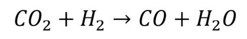
The next step is to convert this carbon dioxide into carbon monoxide. This is done by a process that is referred to as ‘reverse water gas shift’ (RWGS). The RWGS process converts carbon dioxide and hydrogen into carbon monoxide and water, as per the following chemical equation:
Note that this process requires a significant amount of heat and note also that the reaction of carbon dioxide with hydrogen can also produce methane, which has to be suppressed with a selective catalyst.
The other ingredient for synthetic fuel production is hydrogen, which is obtained by the electrolysis of water. This process takes place in an electrolyser and involves the use of electricity to break water down into hydrogen and oxygen.
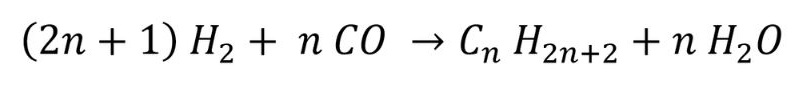
The final step is to carry out a catalytic chemical process that takes the carbon dioxide that has been captured from the air and turned into carbon monoxide via the RWGS reaction, adds it to the hydrogen that has been obtained by electrolysis of water, and creates the required hydrocarbon (plus a number of other by-products, such as water).
This chemical process is called Fischer-Tropsch synthesis, in recognition of two German inventors, Franz Fischer and Hans Tropsch, who pioneered this process in the 1920s.
The underlying chemical formula for this process is:
where n is an integer. Different hydrocarbons can be created, by changing the value of n – for example, if n is 1 then methane is produced. Changing the catalyst, temperature and type of process will create different hydrocarbons. Almost any hydrocarbon can be manufactured, such as plastics, gasoline and lubricants.
The catalyst is based on what are called transition metals, which are typically nickel, iron, cobalt and ruthenium. Nickel is used for the formation of methane, whereas iron is used for the production of hydrocarbons that are created with a lower ratio of hydrogen to carbon monoxide. Ruthenium is usually prohibitively expensive for use as a catalyst in most applications.
Lowe reports that cobalt is commonly chosen as a catalyst for the production of gasoline but would not disclose its own choice of catalyst – this would appear to be part of the company’s ‘secret formula’.
The Fischer-Tropsch process is highly exothermic, creating a large amount of heat. As a result, the company mentions that the overall efficiency of the chemical energy that is created in the synthetic fuel is only around 40 to 45%.
The other issue is of course cost. At the moment the cost of the production of synthetic fuel is higher than that of fossil fuel. As an example, Lowe mentioned that their SAF (sustainable aviation fuel) is currently four times the price of regular jet fuel. This high price is largely down to the relatively low volume that sustainable fuel is currently made in. Lowe drew a parallel with the excessive costs of energy that was derived from the early wind farms, again due to the initial low number of such power sources. Lowe was confident that the costs of its fuel will drop when the volume of fuel produced is increased.
Aside from the carbon-neutral aspect with sustainable fuels, there is one other advantage with regards to emissions from combustion of such fuels in an IC engine. Obviously, the combustion of this fuel creates the primary products of water and carbon dioxide, but as there are no non-hydrocarbons present in the combustion, there are lower levels of particulates and nitrous oxide present in the emissions. Also, as there is no sulphur present, there have been favourable comments about the improvements in the smell of the fuel.
Summary
Sustainable fuels and lubricants will play a pivotal role in the decarbonising of our transportation in the coming years and decades. Rebecca Mann of Coryton observes that 1 tonne of carbon dioxide that is saved today is equivalent to having to save 30 tonnes in 2050. The long term benefits of reducing the carbon footprint of vehicles on the road today will be extremely powerful.
Bio-synthetic fuels and lubricants use biomass that has captured carbon dioxide from the atmosphere. Synthetic fuels and lubricants replicate the process of photosynthesis that was used to create fossil fuels – Paddy Lowe of Zero Petroleum notes that they can complete a task in 3 minutes that nature took six million years to do!
Motorsport will play a vital role in the transition to these sustainable fuels and lubricants. Jean-François Toulisse of TotalEnergies says, “In terms of motorsport activities, we can see that more and more championships are looking for sustainable fuels and lubricants for the near future of their series. This is clearly a beneficial solution to the environment, whilst also keeping the spirit of IC engines alive with the fans.
“EV powertrains won’t be the only solution for motorsport. We are not here to say which energy will be the best on track, but we will see all kind of solutions (biofuels, synthetic fuels and electricity) on the track in the years to come!”
Mann leaves us with a parting word on the future for IC engines that sustainable fuels and lubricants could be a significant part of. “It’s our belief that we need a range of solutions working together to help meet our net-zero target and that sustainable fuels could play a significant role in the mix.
“Across the world there are lots of great examples of sustainable fuels and lubricants working well in action, and there’s a great deal of development work underway. Much of what we’re working on we can’t disclose. But we’re constantly exploring new innovations and ideas to push the sector forward. We’re driven by our mission to create a better future.”
2. Savage, D. F., Way, J., Silver, P. A. (2008) “Defossiling Fuel: How Synthetic Biology Can Transform Biofuel Production” ACS Chemical Biology 3(1):12-16.
Acknowledgements
I’d like to thank Rebecca Mann of Coryton, Jean-François Toulisse of TotalEnergies, Mike Bassett of MAHLE Powertrain, Rick Lee of Evolve Lubricants, Benjamin Cuyt of P1 Fuels, Paddy Lowe of Zero Petroleum, and Yann Labia of Haltermann Carless for their help with researching this article.
The geometry of the head of an inlet or exhaust valve is all about engineering compromises. One compromise is that the head has to be as light as as possible and yet also be as strong as possible. Another compromise is that the head has to seal off the combustion chamber when closed and yet also provide minimal restriction to gas flow when open. And all of this has to be achieved while the valve is subject to extremely high operating temperatures and loads.
Most valve designs begin life with just the basic dimensions of valve head diameter, stem diameter and stem length. The valve head diameter is usually a function of the cylinder bore size, and is maximised as much as possible for two reasons: increased gas flow plus a larger seating area for the valve head (hence a lower seating pressure).
Valve Head Design Terms
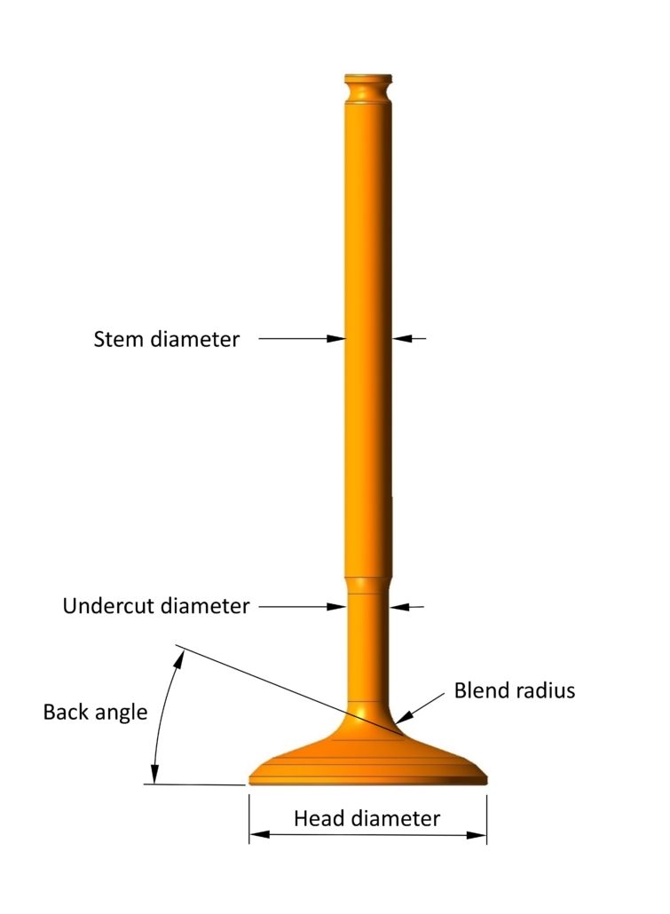
Once the basic geometry of the valve has been decided, the designer must then focus on the more detailed area of the stem radius and the profile of the back of the valve head, both of which are of utmost importance to maximise the strength of the valve and minimise the blockage in the gas flow.
As shown above, working down the stem towards the valve head, there is usually an undercut diameter so that the stem grinding wheel doesn’t foul on the back of the valve head. The surface finish and cylindricity of the stem is vital to ensure that the stem seal functions correctly, so the stem needs to be ground and sometimes polished.
A continuous blend radius then joins the undercut diameter (if present) or the stem diameter to the conical straight section of the back profile. The back angle is defined as the angle between this straight profile and the face of the valve head. Some valves have a large convex radius instead of a straight back angle.
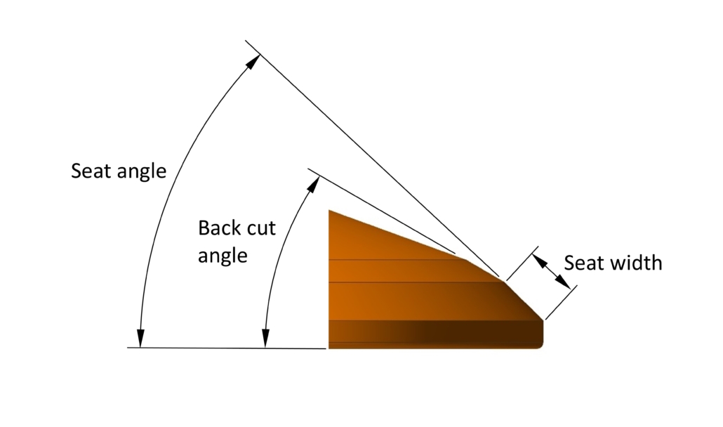
We then come to the seat angle, the conical face that contacts the valve seat in the cylinder head, which is usually in the region of 45° to the face of the valve. The width (and therefore area) of the seat face is kept as small as possible to maximise gas flow, but large enough to withstand the compressive stresses that the landing valve will impose. It is sometimes preceded by a small straight segment called the back cut angle, commonly at 30° to the face of the valve, which helps to lessen the transition between the back angle and the seat angle.
Finally we come to the small radius between the outer diameter of the valve head to the valve face, which is often overlooked but can play a pivotal role in the flow of gases around the valve head.
So, the design of the valve head is far from simple. Undercut diameter, blend radius and back angle must all be carefully chosen, and all three parameters are a compromise between strength and gas flow. In general, stresses are reduced with larger stem diameters and blend radii, to the detriment of gas flow. A steeper back angle normally results in better flow but increases the mass of the head significantly, increasing stresses higher up.
Turbulence
Given that the head of the valve will always be obstructing the gas flow, valve designers have been busy over the years with finding ways to minimise the blockage from the valve head, and in the case of the inlet valve even exploit the presence of the profiled back of the valve head, ultimately to improve combustion.
Combustion efficiency depends on what are colloquially called the three Ts – time, temperature and turbulence. For reasons that are beyond the scope of this article, the amount of turbulence in the combustion chamber has proved to be critical to increasing flame velocities to achieve a good propagation of the flame front.
With a flow rate of more than 75 m/s past the inlet valve in some race engines, all inlet valves will generate an element of turbulence. The type of turbulence depends on the number of valves per cylinder, creating either a swirl type of turbulence or a tumbling type. In truth, both swirl and tumble turbulences are sought, although some engine designs favour one over the other.
Intuitively, it would make sense for the transition between the various segments of the profile to be as smooth as possible. In reality though, many inlet valve designs incorporate sharp edges to break up the gas flow and promote turbulence.
Sharp Edge Step
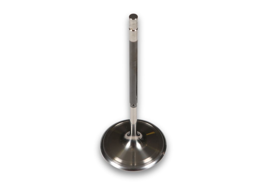
Going one step further, some the heads of some inlet valves also include a raised (but very shallow) circular step or lip with a sharp edge to disrupt the gas flow, just ahead of the seat face.
The lip doesn’t need to be very high at all to ‘trip’ the gas flow as it enters the combustion chamber. The turbulence created has been found to assist the flow of the gas around the corner of the valve head and across the face of the valve.
Shallowing the back angle of the valve head results in a lower mass, and this is taken to the extreme when the valve head begins to resemble a disc. In such cases the lip has been reported to be of benefit because it can create a circulating turbulent area ahead of the lip in the blend radius, lessening the effect of the shallow back angle.
Whatever the reasons for its presence, the lip needs to have an extremely sharp corner, and perhaps one reason why this feature isn’t seen in roadcars is because carbon build-up over time will fill the corner of the lip, diminishing the influence of the edge. Also, the lip is often angled towards the blend radius, making mass-production machining extremely difficult.
Swirl Polishing
A number of valve manufacturers finish the blend radius between the valve head and stem with a detailed polishing operation, commonly known as swirl polishing. As the name suggests, this creates a polished surface with very fine marks spiralling outwards. Traditionally this has been done by hand but now manufacturers are starting to use CNC machines to replicate the swirl polishing, resulting in a more consistent process.
The polishing removes any excess forging material or machining marks, both of which will act as stress raisers that can drastically weaken the valve. Another reason put forward for swirl polishing is that the spiralling marks will create a vortex effect in the gas flow, leading to turbulence. Although the gains in gas flow might be small, the effect of removing raised material from the blend radius can only assist with better gas flow.
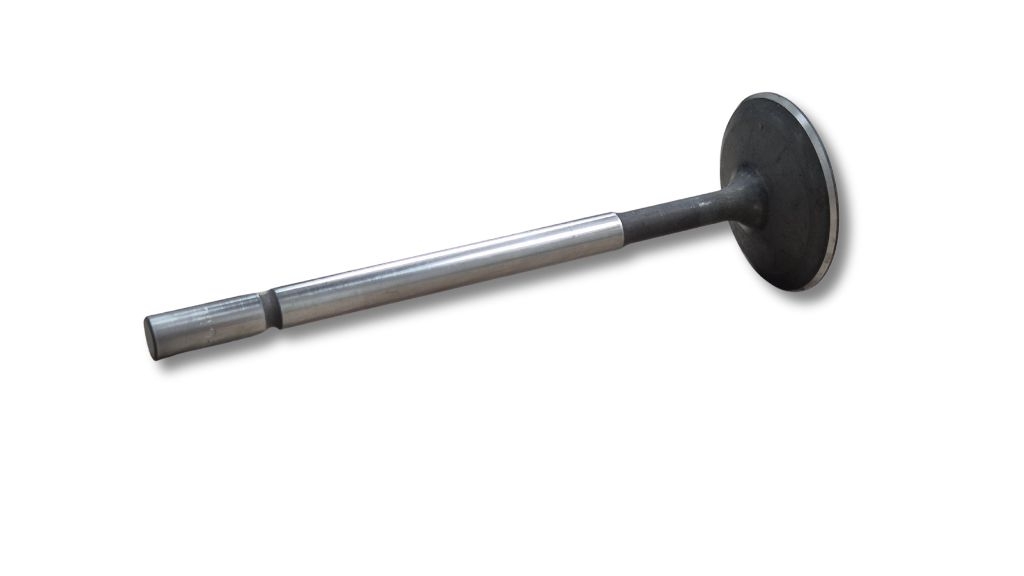
Undercut
Another method for improving gas flow past the valve is to reduce the diameter of the stem just above the blend radius (like on our DFV inlet valve pictured below). As mentioned, it is common to have an undercut diameter here anyway so that the stem diameter can be ground.
A reduced undercut diameter will make it easier for air to flow down the port onto the back of the valve (in the case of the inlet valve) and to flow off of the back of the valve and up the port (in the case of the exhaust valve). Combining an undercut diameter with swirl polishing to an existing valve is reported to give an instant improvement in airflow tests.
Hollow Valves
Hollow valves offer two significant advantages – mass reduction and heat dissipation. Some valves have a cylindrical bore in just the stem, whereas others have the hollow cavity extend into the head – usually, the latter is only possible to create by forging.
If the mass of the valve can be reduced then there is a corresponding reduction in the reciprocating forces needed to move and stop the valve. The forces to move the valve are provided by the cam lobe pushing the valve down and by the valve spring pulling the valve back up. The valve seats have to provide a reactionary force to stop the valve moving upwards.
So, if we can reduce the valve mass, this can potentially lower the cam lobe pressure, lessen the spring forces (and hence, in the case of wire springs, minimise the stress in the coils) and decrease the valve seat pressures. Lower pressure at the cam lobe means less friction too, thereby aiding the reduction of wear in the lobe and follower surfaces. Or, as most race engine designers would prefer, the opportunity to run at faster speeds and with more aggressive cam profiles for improved performance.
The second advantage of hollow valves is that the internal cavity can be partially filled with a cooling agent, such as sodium or sodium potassium. The benefit of increased valve cooling has become more prevalent with the move to small-displacement turbocharged engines. Even worse for valve temperatures, turbo boost levels have risen, resulting in more heat being transferred to the valves.
Exhaust valves in particular have suffered with ever-increasing temperatures, but the switch to coolants inside hollow valves reduces the operating temperatures and opens up the possibilities of running hotter exhaust gases or using materials that might otherwise have failed at high temperatures, such as titanium.
Exhaust valves will transfer heat to the cylinder head through seat contact, but sometimes the materials chosen for valves and seats end up having low thermal conductivity, which is another reason for implementing cooled hollow valves. The coolant in a hollow valve can move heat up the stem of the valve and reduce the amount of heat transferred across to the seat.
Hollow valves are normally only partially filled with molten coolant, allowing the coolant to slosh up and down the valve as the valve reciprocates. Somewhat fortuitously, the coolant is at the bottom of the valve when the valve is pushed open and the valve head is hottest, and it then moves to the top of the stem when the valve is stopped suddenly by the seat and closes, transferring heat to the surrounding valve guide.
Sodium is very good material to use as it solid at room temperature and so can be squeezed into the open hole in the valve. Once the valve temperature approaches 100 °C the sodium will melt and move inside the valve in the manner described above. It has the added benefit over alternative coolants because it has a relatively high boiling point, of 883 °C, which makes it suitable for most exhaust valve applications.
Rod length is defined as the distance between the small end and big end bore centres. Combined with the stroke, which is the distance that the piston travels, the rod length is an important parameter in the kinematics of the cranktrain. The rod length and stroke for an engine are sometimes expressed as the ‘rod ratio’, which is the rod length divided by the stroke.
It seems counterintuitive to increase the rod length. After all, this means that the deck height increases and the engine gets taller. But if the engine has already been designed, then one common aftermarket trick to get more power is to try and increase the rod length.
Here are four reasons why a longer rod length can help improve performance.
1. Longer Dwell
An increase in rod length allows the piston to spend more time near TDC (top dead centre). The change in geometry means that the compression can be held for around half a degree longer. It might not sound much, but that small increase in time can improve combustion efficiency and eek out a bit more power from the combustion process. This effect is normally more pronounced above the mid-range RPM.
2. Reduced Skirt Load
Increasing the rod length will reduce what is called “rod angularity”, which is the angle of the rod to the cylinder axis. This reduces the side load on the piston skirt, which helps in a number of ways. For a start, there will be less frictional losses between the skirt and the cylinder wall, which means that there will be more power transmitted to the crankshaft.
Another beneficial by-product that comes from reduced skirt load is an improvement in NVH (noise, vibration and harmonics). The YB piston already has an offset pin bore to help stop it sounding like a diesel tractor engine on a cold day, and long rods do a similar thing.
3. Reduced Secondary Forces
The secondary forces that are created by the reciprocating mass (which is a proportion of the rod mass plus the piston mass) are inversely proportional to the rod ratio. If the stroke is fixed and the rod length is increased then the rod ratio goes up and the secondary forces come down.
These secondary forces act at twice engine speed and as such can’t be balanced out by the crankshaft counterweights. Reducing the secondary forces by increasing the rod length helps to improve the balancing of the bottom end forces, which will reduce vibration.
4. Reduced Piston Mass
For a given deck height, increasing the rod length means that the pin bore needs to be pushed higher up in the piston. This can often lead to a lighter piston – in the case of our YB pistons, the mass reduces by 38g.
Of course, the rod mass will increase so there might not be an overall weight saving, but reducing the piston mass has a knock-on reduction in the inertia forces that the piston imparts on the gudgeon pin when the piston reaches TDC.
This means that there is less load, and hence less stress, in the pin bore, which can help to increase the durability of the piston.
The Long & The Short of It
Of course, the proof is in the pudding. Does running a longer rod actually give more performance? Well, one of our customers kindly tested the YB engine in both standard rod length and long rod length forms, and gave us this feedback. “We saw around between 5% and 10% increase in torque between the midrange and the top end of the power curve”, says the customer.
Running a longer rod length not only offers the potential of extra torque, but also can improve reliability and reduce NVH.
If you’d like to know more about the benefits of switching to a longer con rod then please get in touch.
https://modatek.co.uk/wp-content/uploads/2024/10/Con-Rod-Length-edited.jpg5761024Matthew Granthttps://modatek.co.uk/wp-content/uploads/2024/02/Modatek-Logo-V3-Logo-for-Header-2-300x137.jpgMatthew Grant2024-10-14 14:41:352025-06-03 15:09:34CON ROD LENGTH TECH
At the heart of an engine’s lubrication system is the oil pump, which has to continuously move oil around the complex maze of passageways inside the engine. A correctly working oil pump is vital for engine health – just one instantaneous drop in oil pressure could be catastrophic for the lubrication of bearings. But how do oil pumps work, and what are the different types of pumps that can be used on race engines?
The pump moves the lubrication fluid by trapping the fluid between moving elements. Irrespective of the type of pumping elements used, these pumps are commonly referred to as positive-displacement pumps. In a positive-displacement pump, the internal elements move to create an open void that expands and fills with the fluid. The elements then move, taking the fluid with them, after which the elements compress the volume of fluid, forcing it out of the pump.
Positive-displacement pumps can be broken down into two groups: rotating and reciprocating. The vast majority of oil pumps we find on race engines tend to be of the rotating variety, as the rotating action of the elements gives a relatively smooth flow of oil and can be designed to be compact and light. Rotary drive can be provided directly from the crankshaft via a gear, belt or chain, making them easy to package into either a new clean-sheet engine design or onto an existing engine’s architecture.
Internal Gear Pumps
The anatomy of an internal gear pump is relatively simple – an inner gear with external teeth runs inside an outer gear with internal teeth. The outer gear is housed in a cylindrical body with inlet and outlet ports on the end. The inner gear will typically have one tooth fewer than the outer gear, and the two gears run on fixed eccentric axis. When the two gears rotate, the volume created between the meshing teeth will expand and contract to pump the fluid.
Internal gear pumps include a crescent shape in the void under the inner gear. This crescent will divide the two rotors and act as a seal between the high- and low-pressure areas.
Gerotor Pumps
A sub-set of internal gear pumps is the gerotor pump, short for generated rotor. The gerotor design does away with the crescent, creating a compact and simple solution, like our Cosworth YB oil pump.
With only two moving parts, gerotor pumps are a simple and versatile product, and it’s easy to see why they have been so popular over the years in road as well as race engines. Gerotor pumps are especially common as oil pressure pumps, as they can have a lower fluctuation in output pressure when compared with an external gear pump.
Another plus point for the gerotor design is that the housing needs only one cylindrical bore machining in it to accommodate the outer gear, unlike an external gear or lobe pump which needs two rotor bores. And the packaging of one gear inside another means the overall size of a gerotor pump can be quite small compared with other pump options.
One other advantage that the gerotor pump has over other types is thanks to the design of the rotor teeth. These can have extremely tight clearances, which leads to less leakage between the teeth and hence better efficiency.
Note though that the tight clearances can also be detrimental, as the rotors are more prone to damage from debris. That makes gerotor pumps less attractive for scavenge pumps, where debris in the oil scavenged from crankcase is more prevalent.
Surface wear on the teeth of gerotor pumps can also be less than that seen on those of external gear pumps. That is because the relative velocity between the inner and outer gears is quite low. Take for example a gerotor pump with five teeth in the outer rotor and four in the inner rotor. At a pump speed of 2,000 rpm the relative rotational speed between the inner and outer rotors will be only 400 rpm.
Trochoid Gear Profiles
The devil is of course in the detail, and in the design of the gear profiles this maxim is especially true. Most gear profiles in internal gear pumps are from the family of trochoid curves, which is the path created by a fixed point on a circle rolling along a straight line.
A dissection of the mathematical formulae used to generate a member of the trochoid curve group is beyond the scope of this blog, but we can touch on the definition of some of the types of trochoid curves and look at a few of the different gear profiles used by manufacturers for their ranges of gerotor pumps.
The term ‘trochoid’ actually covers a number of different subsets of curves, including epitrochoids and hypotrochoids. An epitrochoid curve is formed by the movement of a fixed point on one circle rolling around the outside of another circle. By contrast, a hypotrochoid curve is created by rolling one circle around the inside of another.
If you’ve ever played with a Spirograph toy then you will remember the motion of a pen pushed through a hole in the small cog as it rotates inside or outside a larger toothed disc. These curves are actually epitrochoids and hypotrochoids.
In a standard trochoid profile gear set, the inner gear is epitrochoidal but the outer gear isn’t and hence the profiles of the inner and outer gear teeth don’t mesh perfectly. As a result, standard trochoid profile gear sets can tend to have lower sealing properties (some of the oil from the high-pressure side will escape back to the low-pressure side) when compared with other gear profiles, giving rise to a lower volumetric efficiency.
A true epitrochoidal gear set has epitrochoidal profiles on both the inner and outer gears, and the profiles will fit perfectly inside one another when they mesh. This variant will provide a good compromise between volumetric efficiency and resistance to wear. Conversely, this style of profile can be the most prone to damage from debris, as there are no gaps for the foreign material to reside in when it passes through the teeth.
Hypertrochoid curves aren’t normally used to construct the gear profiles on automotive internal gear pumps. That is mainly because such profiles can create abrupt intersections between the lobes, which can lead to premature wear. The sharp faces of the inner gear can quickly damage the lobes of the outer once they are subject to the high speeds seen in a race engine oil pump.
One other profile used in gerotor pumps is termed the K-floid, which is essentially a hypotrochoid curve and an epitrochoid curve stitched together. K-floid gear profiles are reputed to offer good resistance to debris, but they can end up with low volumetric efficiency and are more vulnerable to wear when compared with other profiles.
The most prevalent gear profiles on the market are generated from trochoid curves with epitrochoidal inner gears or matched epitrochoidal inner and outer gears.
Some gerotor pumps also feature an asymmetric tooth profile on the outer gear. This can make then more efficient, but the downside is that the root radius tends to be smaller, leading to large stress concentrations, making them less suitable for high-performance applications.
Tooth Factors
Aside from the tooth profile, there are other changes in geometry that can be altered to increase or decrease flow. The amount of eccentricity will have a knock-on effect on the tooth length, and can weaken the gear. If the eccentricity is changed then the lobe radius of the outer diameter must also be changed to reduce the stress in the lobe.
The number of teeth chosen will have a major impact on pump performance. Fewer teeth mean that the overall diameter of the pump can be smaller, which in turn makes it easier to package in the engine. Fewer teeth also result in a reduction in power loss for a given flow rate, but the downside is that they have to run at a higher rotational speed, which can increase wear.
On the other hand, more teeth will give fewer pressure fluctuations and hence a smoother overall oil pressure. The fluctuation is sometimes referred to as pressure or flow ripple, and is an unwanted side-effect of any positive-displacement pump. The effect of pressure ripple is mechanical vibration in the oil circuit in the engine, which can damage components such as oil hoses, seals, and bearings, so any measures that can minimise pressure ripple are likely to be of great benefit.
External Gear Pumps
External gear pumps consist of two gears laid side by side, with one gear driving the other. The movement of the oil by an external gear pump is similar to that for an internal gear pump, and like the internal gear pump it is the teeth on one gear that drives the teeth on the other.
When the gear teeth come out of mesh they create an expanding volume that is filled by the oil fed from an inlet port. This oil is trapped in the gap between the teeth and the inner diameter of the housing, and as the gear rotates then so too does the oil. The gear teeth then come back into mesh, collapsing the volume of oil and forcing it into the outlet port and out of the pump. Most race engine oil pumps contain spur gears with parallel teeth, but in other applications the gears can be angled in a chevron pattern.
The tooth profile for an external gear pump is different from that used for an internal gear pump. Most external gear pumps contain gears with involute tooth profiles. An involute curve is the spiralling path created by unwinding an imaginary taut string from a stationary circle. The curve is prescribed by a number of inputs, including module, pressure angle, addendum modification coefficient and base circle diameter. All these variables can be adjusted to give the final tooth shape.
External gear pumps will typically have supporting journal shafts at either end of the rotors (as do internal gear and external lobe pumps for that matter), and the shafts run inside bearings or bores in the pump housings and cover. Because the shafts are normally immersed in oil, it is possible to avoid the need for bearings, and in some pump designs they can run directly in the bore so long as the size, cylindricity and positional tolerances of the bores are carefully controlled during manufacture.
However, wear in the journal bore can still sometimes be an issue. As a result, some pumps will have bronze bushes in the housing and cover plate. Further, some pump designs have small drillings to help feed oil from the high-pressure outlet port to the centre of the journal bore for lubrication purposes. That might have a small effect on pump efficiency but it can prolong the pump’s life, as wear in the journal bores can cause the rotating gears to start to lose alignment after an extended period of running.
External Lobe Pumps
A popular solution for scavenge pumps is the external lobe pump, which operates in a similar manner to the external gear pump. The external lobe pump consists of two identical rotors rotating in opposite directions, with lobes that do not contact one another.
They are timed and driven by a pair of gears that are mounted on the same shafts as the lobes, which can be a disadvantage as extra room is needed to house the timing gears. As the lobes come out of mesh they create an expanding volume in the inlet port.
The movement of oil in an external lobe pump follows the same principle as in an external gear pump. The lobes rotate to create an expanding cavity that is filled with oil. The oil rotates around in the lobes until the lobes mesh again, forcing the oil into the outlet port and out of the pump.
External lobe pumps are sometimes referred to as a Roots pump, named after the American inventors and brothers Philander and Francis Marion Roots, who established the Roots Blower company in the 19th century. The lobe concept used in a Roots-type air induction blower is similar to that used by external lobe oil pumps.
External lobe pumps make an excellent choice for scavenging oil out of the engine because they are capable of pumping much larger volumes than could be attained with an external gear pump. This extra pumping capacity means they will also remove the crankcase gases, which creates a beneficial depression in pressure within the crankcase. In addition, because the lobes don’t contact one another, they don’t suffer from wear damage when pumping just air.
Early rotor lobe profiles were generated from a series of radii, but now more complex curves can be constructed to optimise the amount of volume displaced by the meshing lobes. The profiles of the lobes tend to be a mixture of epitrochoid and hypotrochoid curves used in internal gear pumps.
The number of lobes is another source for development. Traditionally, scavenge pumps would have twin lobe rotors, but there has been a trend to increase the number of lobes to three or more per rotor. While two-lobe rotors will have lower frictional losses than multiple-lobe rotors, having more lobes can help the rotor withstand the ingestion of debris.
As already discussed, the disadvantage with any positive-displacement pump is that the teeth come in and out of mesh, resulting in a variation in output pressure. On a lobe pump, one way to alleviate that is by using helical lobes that are twisted rather than straight. Although such helical gears can promote axial forces on the rotor, they have been proven to give a smoother flow of oil at steady speed.
Lobe pumps can be very efficient as they can offer a much larger ratio of displaced volume per unit volume than their geared counterparts (in effect, the volume between the lobes is larger than the volume between the gear teeth). However, there is a chance of more leakage in a lobe pump as the route back between the rotors is less convoluted than that in an internal gear pump.
This is particularly true with a twin-lobed rotor, so the clearance from the tip of one lobe to the base circle of the other needs to be as small as possible. That can only be achieved with precision machining of the rotor profiles and extremely accurate positioning of the rotor bore and journal bores in the housing and cover.
Pump Efficiency
There are a couple of useful parameters to describe how the efficiency of an oil pump: volumetric efficiency and overall efficiency, which are both expressed as a percentage. Both have to be obtained from empirical tests that are normally carried out on a test rig. Typical values of volumetric efficiency and overall efficiency vary markedly depending on the type of pump, and will also change with speed and pressure.
Volumetric efficiency is defined as the ratio of the actual volumetric amount of fluid moved by the pump compared with theoretical volume of fluid that should be moved. The actual volumetric flow rate has to be measured with a flow meter, and it is important to include the flow through the pressure relief valve if one is present.
Complex equations and CFD (computational fluid dynamic) simulations can be derived to determine the theoretical flow rate, but there is a simpler approach that will give a good approximation. First, measure the volume of the gear tooth space; normally this can be determined from a CAD model. The theoretical volumetric flow rate is then the product of the tooth space volume, the number of teeth and the rotational speed of the gear.
The overall efficiency is the ratio of the hydraulic power created by the pump relative to the (input) power required to drive the pump. The input power has to be measured, normally by fitting a torque sensor to the pump drive, and the input power is then the product of the measured torque and the rotational speed of the pump drive. The hydraulic power is then the product of the measured flow rate and the pressure rise delivered by the pump.
The goal for most race engine oil pump designers is to minimise any losses in the amount of hydraulic power generated by the pump. Some of these are attributed to the journal shafts running in the housing, cover and seals.
Further, in a gerotor pump, most of the mechanical losses come from viscous drag on the outer diameter of the outer gear and its end faces, hence such pumps will sometimes incorporate low-friction coatings in the bore and faces of the housing and cover. In a gerotor pump, reducing the outer diameter of the outer gear can be very beneficial to reducing viscous drag.
The clearances between the inner and outer rotors and the housing will also have a large effect on both volumetric and overall efficiency, so the lengths and diameters of the rotors and housing bore have to be tightly controlled. For example, most gerotors for oil pressure pumps will have clearances of around 0.1 mm radially between the outer rotor and the housing, 0.05 mm axially between the rotors and the housing, and tip clearances of around 0.08 mm.
These clearances are compounded by tolerance stack-up of multiple parts. For example, to achieve the axial clearance of 0.05 mm the tolerance on the length of rotors and the depth of the housing bore have to be around 0.025 mm per part. Minimal clearance will mean less loss due to leakage of the oil across the end faces from the pressure side to the suction side, but too little clearance can cause binding of the rotor. It is also possible to have debris trapped between these end faces if there is insufficient clearance.
Pressure Control
Undesirable thrust loads on the rotor end faces can arise if there are excessive fluid pressures inside the pump, resulting in sometimes catastrophic seizure of rotors. Most pump manufacturers have their own design methods to avoid this build-up of back-pressure, with small ports and galleries helping to drain the oil from the faces.
Some oil pump designs include small, shallow pockets in the end faces of the housing near to where the gears mesh. These are intended to relieve the lateral forces created between meshing gears, and which would otherwise cause the rotor and journals to start to bind and seize in their housing bores.
Also, most oil pressure pumps will incorporate a pressure relief or regulation valve to prevent over-pressurisation (you can read our technical blog on pressure relief valves here). As the output pressure is proportional to the pump speed, the valves are designed to operate at a pre-selected engine speed.
Most pressure relief valves consist of a spring-loaded piston. The spring rate and length are chosen so that the piston moves when the oil pressure reaches a desired value, and the piston will then slide to open a gallery to divert oil away from the high-pressure outlet, thereby capping the rise in pressure.
When designing pressure relief valves, consideration has to be given to where the by-passed oil will return to. Some designs will return the oil back to the pump inlet, whereas others will recirculate the oil back into the engine. Feeding oil back into the inlet can increase the oil temperature inside the pump and can also aerate the oil, which are both undesirable side effects.
Material Selection
As with any critical engine component in a race engine, the choice of material for the individual components in an oil pump needs careful consideration. While they may not be subject to the loads and stresses seen in other engine parts, oil pump housings still have to be able to withstand the stresses and deflections induced by the rotating internal components. And although a cracked oil pump housing or cover might not be catastrophic to start with, the consequences are still serious, as a gradual leakage of oil or reduction in oil pressure can eventually lead to engine failure.
Oil pump housings and covers are therefore normally made from a very high-grade aluminium alloy, with careful design to ensure that the rotor and journal bores remain as rigid as possible under all operating conditions. Aluminium is also an excellent material to machine, which can make it easier to achieve the very tight machining tolerances required. Some pump housings and covers are also anodised for protection against the harsh environments they find themselves in.
The rotors for both an internal and an external gear pump will be subject to very high contract stresses when the gear teeth mesh. Consequently, quite often they are made from high-grade steels, similar to gears from other drive systems in the engine.
There is however a fundamental problem when running steel rotors in an aluminium housing, and that is the different thermal expansion rates of the two materials. Aluminium has a thermal expansion coefficient that is more than twice that of steel, meaning that as the oil pump temperature increases, the housing will grow more than the rotors, which will lead to increased clearances, increased leakage and consequently a reduction in efficiency.
Some pumps will feature bronze or brass as the rotor material, as these materials are closer to aluminium in thermal expansion rates. Conversely, some pumps with steel rotors will have cast iron housings that have similar thermal expansion coefficients.
The rotors in an external lobe pump can enjoy a slightly easier life then their geared counterparts because the lobes don’t come into contact with one another, so there is no contact loading to worry about. This means that wear isn’t an issue on the lobes, and the materials used can be as light as possible, for example aluminium alloy or even carbon fibre. However, caution has to be applied to the wear properties of the lobes as they will have to cope with any debris sucked in from the crankcase, hence the need for good filtration on the scavenge pump inlet.
Coatings are another option that manufacturers can turn to, either to combat wear between the meshing gear teeth or to reduce friction between running surfaces, particularly between the end faces of the rotors and the flat faces of the housing and cover. PVD-applied coatings such as DLC can help to reduce wear, and PTFE-type coatings have been used over the years to reduce friction.
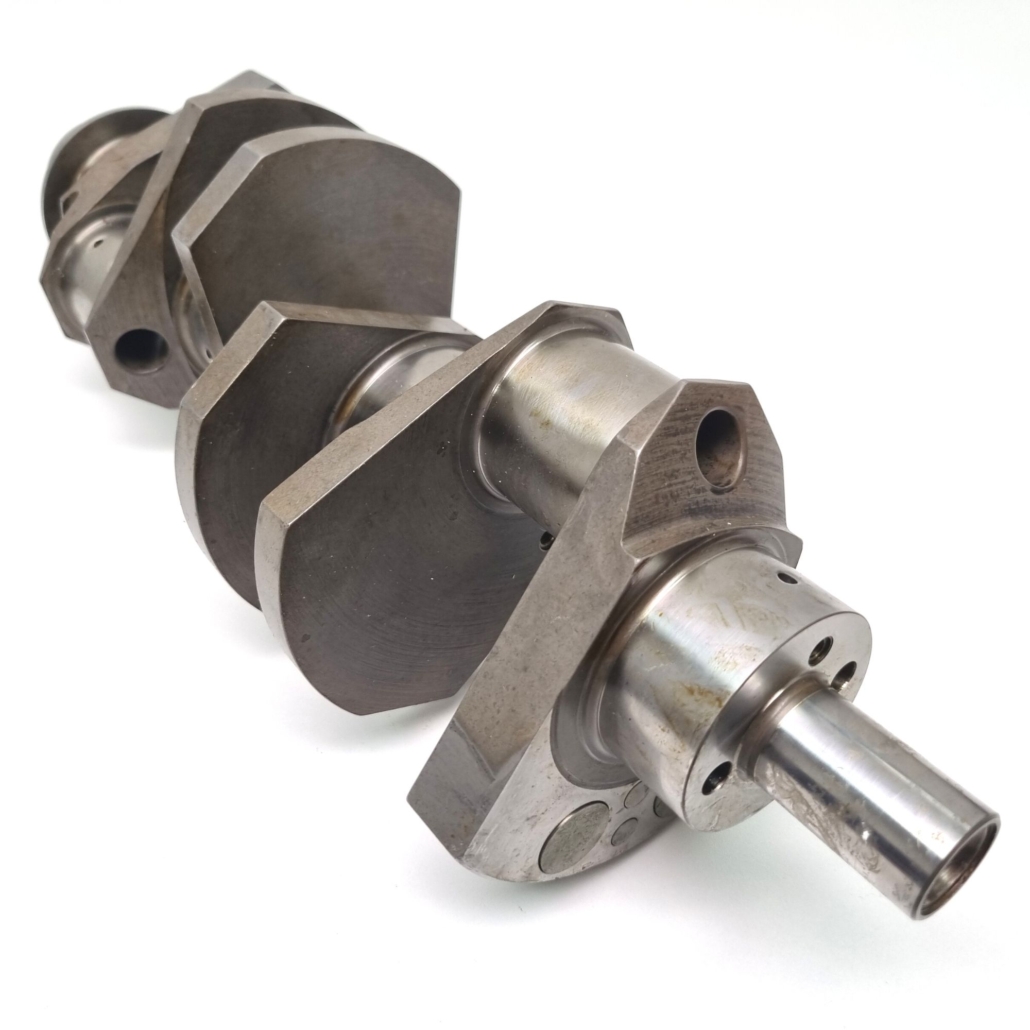
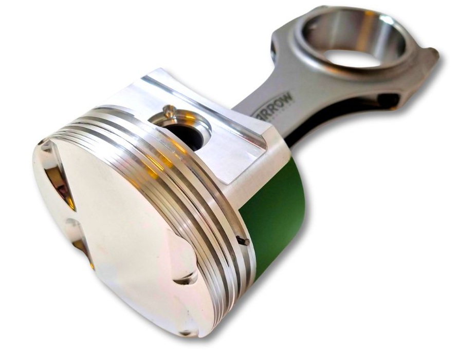
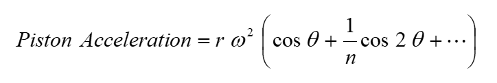
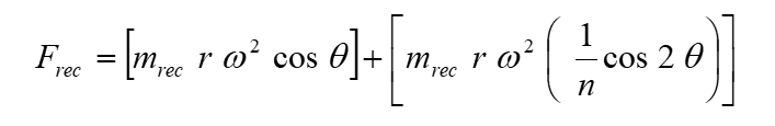
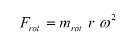
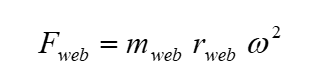
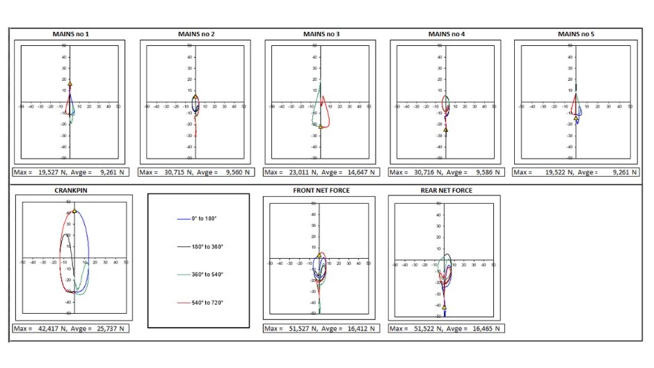
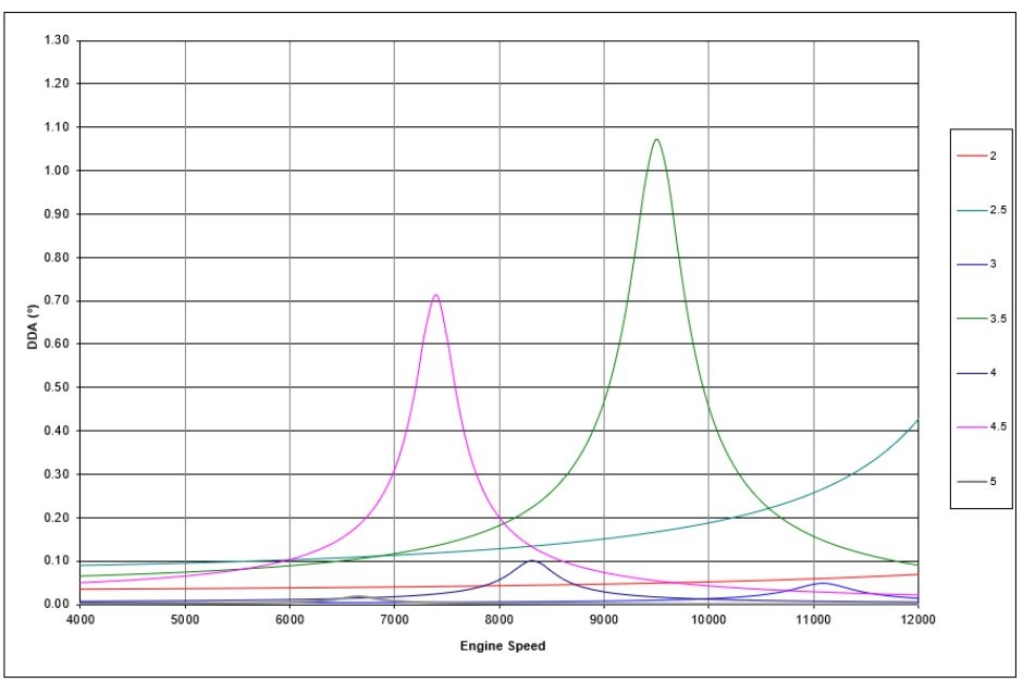

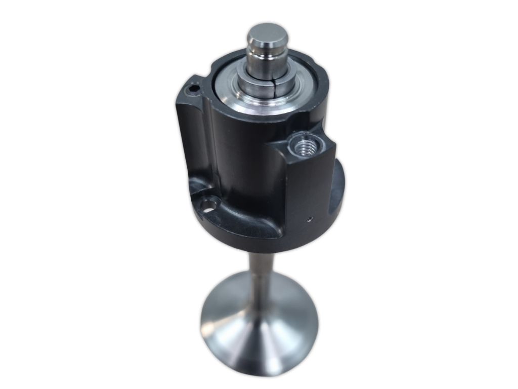
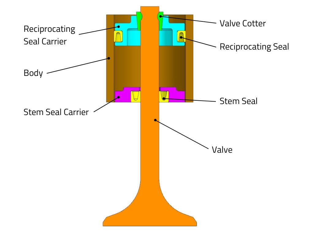
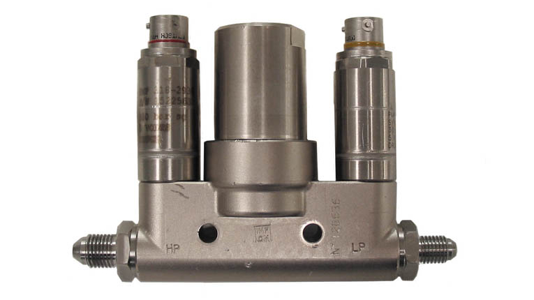
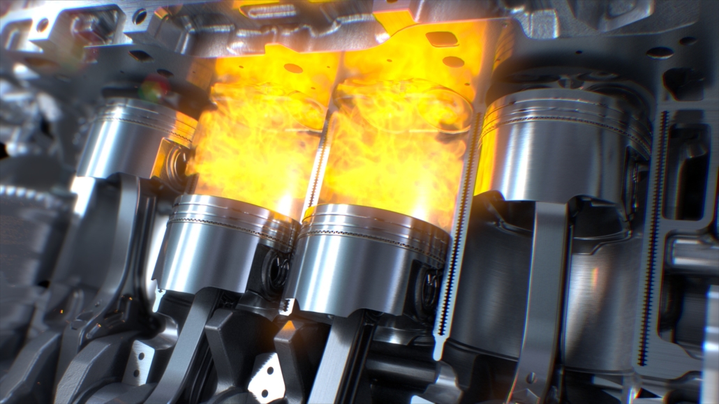
 )
)