Plain journal crank bearings rely on fluid-film lubrication to keep the bearing surfaces apart. Without a steady supply of lubricant, the bearing will prematurely wear and this could lead to seizure of the bearing surfaces and engine failure.
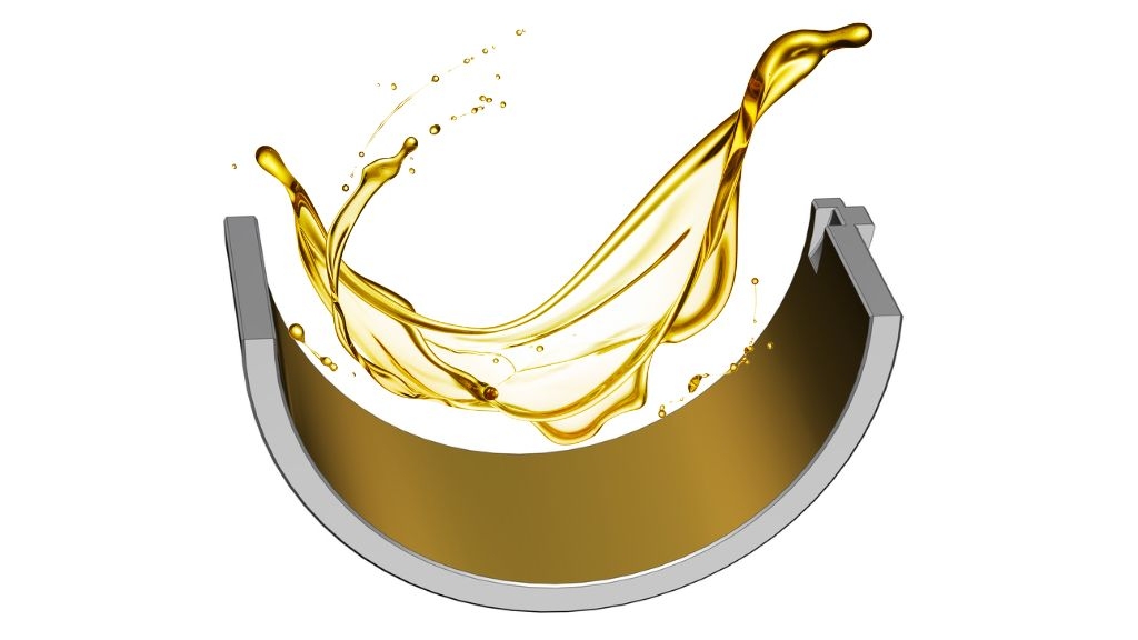
With fluid-film lubrication, the load-carrying ability of the bearing is made possible by the rotational movement of the journal inside the bearing, which generates a wedge of oil to create extremely high pressures. As oil is almost incompressible, it can keep the journal and bearing separated and support the very high loads we have already discussed.
Tribologists will often refer to three different modes or regimes of lubrication – boundary, mixed and hydrodynamic. The mode is dependent on the speed of the journal, the viscosity of the oil and the magnitude of the applied load.
Most of the time, the bearing will be operating with hydrodynamic lubrication, whereby the relative motion of the two surfaces is enough to create the thin, wedge-shaped oil film just mentioned that will support the loads being transmitted and keep the journal and bearing surfaces completely separate.
In boundary lubrication, conversely, the two sliding surfaces are in contact with one another. This can occur at low engine speed, such as during engine start-up or shut-down, and in the worst case at normal operating speed when the applied load is too high for the oil film to withstand, or when the viscosity of the oil is too low.
Generally, boundary lubrication needs to be reduced as much as possible, otherwise the contact between the two surfaces will lead to abrasion and wear. Engine designers are renowned for wanting to maximise engine speed, and hence the bearings are subjected to higher and higher inertia loads, so it falls to the only other variable, viscosity, to reduce the chances of boundary lubrication.
If the viscosity is too low then boundary lubrication can occur; if it is too high then there will be an increase in the molecular friction within the oil, which in turn will increase the temperature of the oil, reducing its efficiency.
The mode between the boundary and hydrodynamic lubrication regimes is termed mixed lubrication. As mentioned, when the relative sliding speed of the two surfaces increases, a wedge of oil begins to form. This wedge starts to separate the asperities of the two surfaces and the oil film’s thickness starts to increase, drastically reducing the coefficient of friction. When there is still some contact between the asperities, this is referred to as mixed lubrication.
Stribeck Plot
The three modes of lubrication can be visualised with the help of a Stribeck curve (shown below), which shows how the lubrication regime is influenced by the speed, viscosity and load.
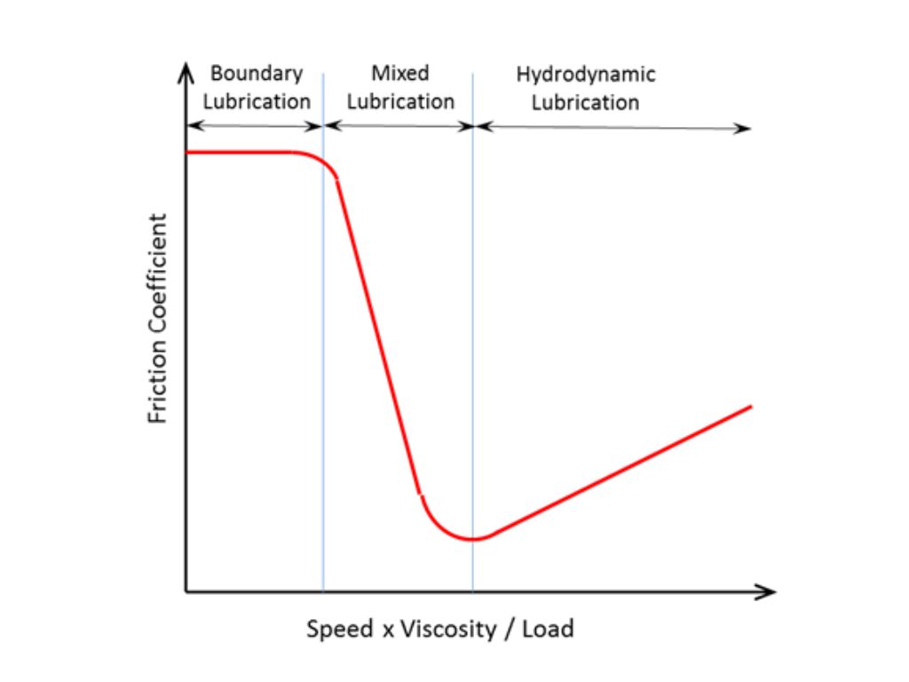
This theory is one of the fundamental concepts in the field of tribology, and was developed by German engineer Richard Stribeck for the railway industry at the turn of the 20th century. It is also attributed to other engineers and scientists, most notably American engineer Mayo Hersey, who performed similar research at the same time as Stribeck.
Simply put, a Stribeck curve plots a non-dimensional lubrication parameter along the x axis and the friction coefficient (on a logarithmic scale) along the y axis. The non-dimensional lubrication parameter is the product of the surface speed and absolute viscosity divided by the unit load, and is often variously referred to as the Hersey number, the bearing operating condition or the bearing parameter. Whatever the terminology though, this parameter increases with speed and viscosity, and is inversely proportional to load.
The curve shows that there is a marked change in friction coefficient between the three modes, as seen by moving along the x axis when one increases speed and/or viscosity and/or reduces load. Friction is highest in the boundary lubrication zone, and falls rapidly throughout the mixed lubrication zone, reaching its lowest point at the onset of the hydrodynamic lubrication mode, and thereafter gradually rises again. The optimum point for speed, viscosity and load is thus at the beginning of the hydrodynamic lubrication regime, where friction is at its lowest.
Elastohydrodynamic Lubrication
There is another regime of lubrication that is considered by bearing manufacturers, and that is elastohydrodynamic lubrication, commonly abbreviated to EHL.
This is a sub-topic of hydrodynamic lubrication. With EHL, a wedge of oil supports the load and keeps the two surfaces apart, but EHL theory also takes into account the microscopic distortion of the two surfaces. EHL is more prevalent where high contact stresses are involved, such as between a cam lobe and follower, but it is now also being considered by crankshaft journal bearing manufacturers.
The computation of EHL becomes such that very specialised software is required to conduct this type of analysis, which involves the Reynolds equation for the oil film (a partial differential equation that defines the pressure distribution of thin viscous fluid films) along with classical elastic deformation equations similar to the ones developed by Hertz.
Most bearing manufacturers will now use FEA to conduct their EHL analysis. The con rod assembly, bearings and crankpin are all modelled as a structural mesh of elements, containing the mechanical properties of each component. This allows the bearing manufacturers to see how the components will distort so that they can correctly predict lubricant behaviour and assess pressure distributions across the running surfaces of the bearings. It is important to note that as with all types of computerised analysis, validation of the theoretical results needs to be sought with rig and engine testing.
Wear
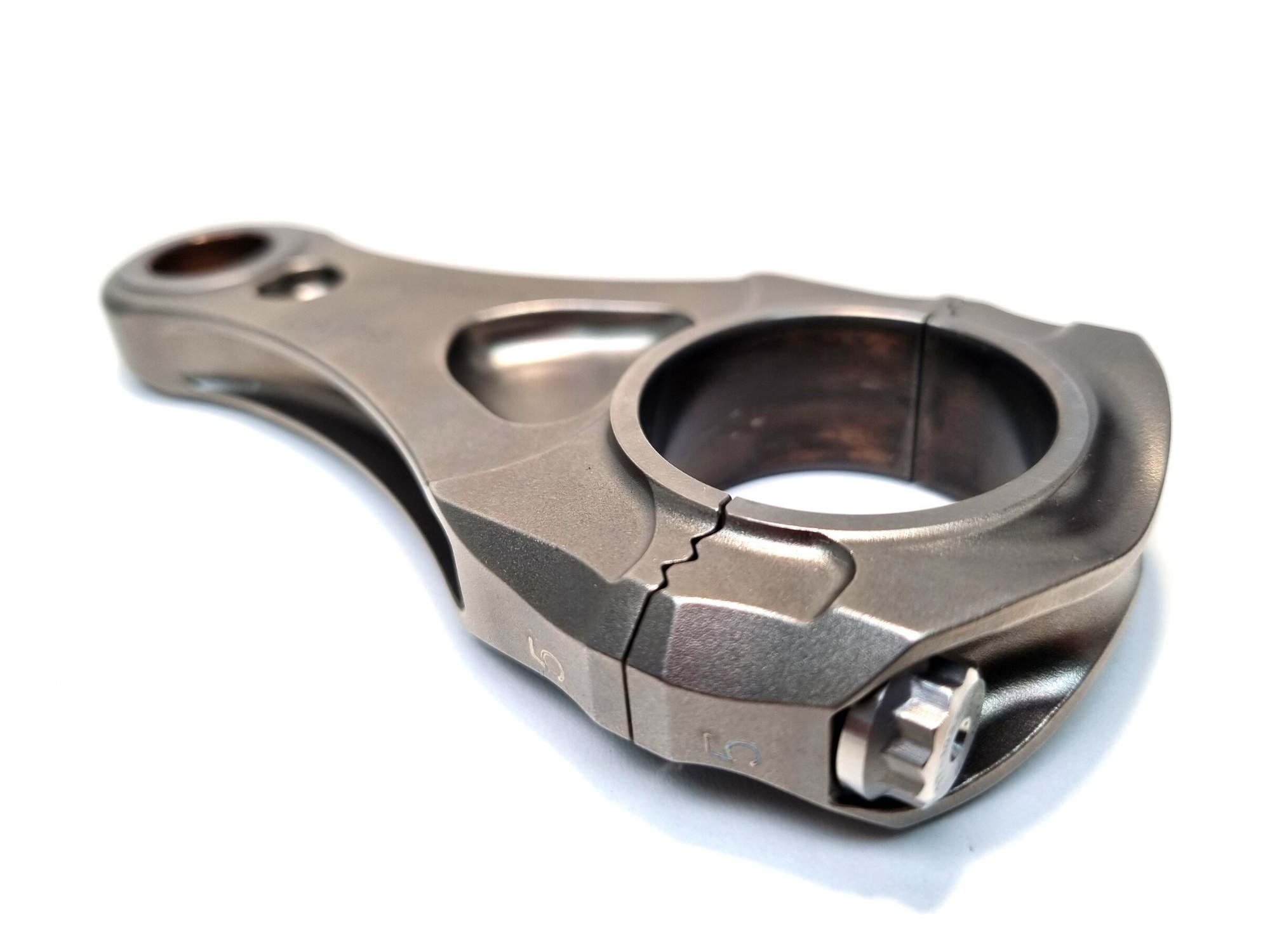
Most journal bearing failures stem from metal-to-metal contact. Usually such wear will be termed ‘wiping’, with large dark brown streaks that smear around the surface indicating excessive oil and metal temperatures. In the worst cases, the overlay (if present) and substrate will start to melt.
This type of wear can be caused by the mode of lubrication falling into either the boundary or mixed regimes. Remember that the lubrication mode is influenced by surface speed, viscosity and load, so a change in one or more of these parameters can be the root case. For example, contamination of the oil with fuel or coolant will reduce its viscosity and can move a normally hydraulic lubrication mode into the mixed zone that is illustrated in the Stribeck plot.
Metal-to-metal contact can also occur if there is insufficient oil supply to the bearing. Most crankpin journal bearings are fed from a drilling in the crankshaft, which in turn is fed oil from the nose or rear of the crankshaft or from drillings that take oil from the mains journals.
Improper positioning of the outlet of the crankpin journal can end up feeding oil into a high-pressure zone, effectively choking the oil supply to the bearing. Alternatively, nose- and rear-fed crankshafts can have poorly designed oilway drillings that have a detrimental effect on oil supply. Some crankshafts seem to have a labyrinth-like network of angled holes criss-crossing down the crank with large pressure losses at each intersection, the result being that the oil pressure at the crankpin journal bearings at the end of the crankshaft is lower than that of their neighbours.
Localised wear marks on the bearing edges can be an indication of misalignment, which might be due to a distorted con rod or crankshaft journal. Engine designers have always tried to minimise crankshaft journal diameters in a bid to save weight and packaging space, but that can come at the expense of crankshaft stiffness. A key indicator of excessive twisting and bending of the crank journals is edge loading and wear on the bearings.
There are other sources for metal-to-metal contact, most of which can be eliminated through care and attention during design and manufacture. For example, poorly thought-out geometric tolerances can lead to misalignment of the bearings onto the crankshaft journals. As regards manufacture, inadequate grinding of the crankpin journals can result in a poor surface finish, chatter marks and even faceted journal shapes that will all increase the chance of metal-to-metal contact.
Cavitation
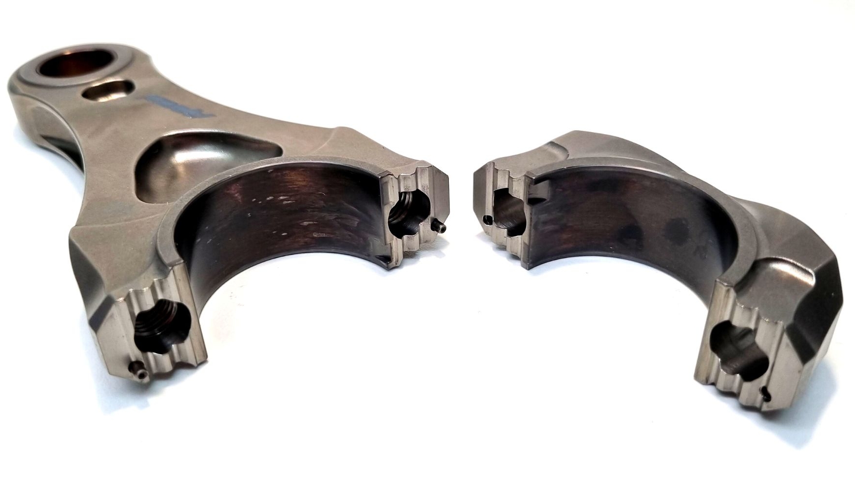
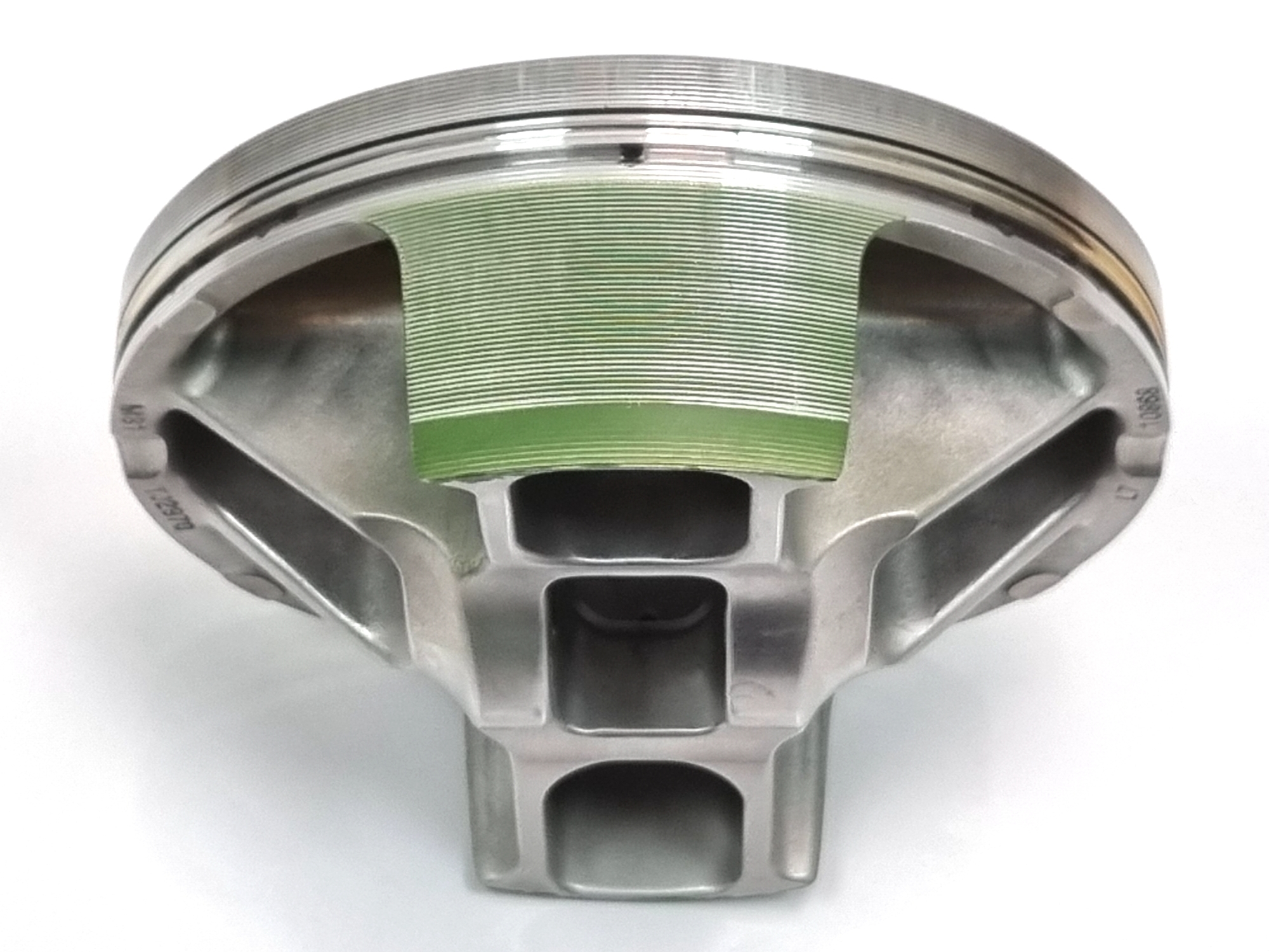
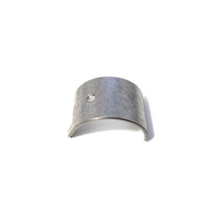
One of the most common forms of erosion that journal bearings will experience comes in the form of cavitation (as evident on the bearings pictured below). Unlike other forms of wear that a bearing might experience, with cavitation there is no metal-to-metal contact.
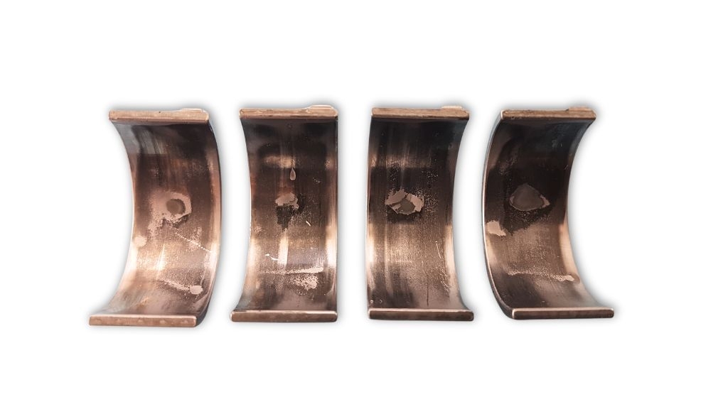
Although mild amounts of cavitation erosion are not uncommon and can be tolerated, if a bearing is subject to too much cavitation then it and the journal can partially or completely seize. Bearing cavitation can be highly destructive in race engines and difficult to diagnose, especially if the bearing has started to seize and any visual evidence is destroyed.
But what causes cavitation, and how can it be reduced or eliminated?
The answer to the first question lies in the behaviour of the oil present between the top of the crankpin journal and the bearing in the con rod half. When the piston approaches TDC it might stretch the con rod, momentarily distorting the circular big-end bore in the rod and cap assembly, with a corresponding distortion of the profile of the inner faces of the bearings.
This distortion creates a low-pressure region between the rod-half bearing and the crankpin journal. In some circumstances, minute vapour bubbles are formed in this region. With the onset of gas loading and the reversal of piston movement, the bubbles are re-pressurised and they contract at extremely fast rates, resulting in the bubbles imploding.
When the bubbles implode, they become liquid and create extremely high local spots of pressure, which lead to microjets that are fired into the surrounding bearing material. These pressure surges are actually strong enough to remove material from the bearing, and if the process is repeated for too long it will create microscopic cavities in the surfaces of the bearing.
Note that although cavitation erosion is more prevalent in con rod half-bearings, it can also be seen in the tag slot area of the cap-half bearing, where there is some geometric relief, and in the upper mains journal bearings, when the bore in the cylinder block assembly distorts under cyclic loading.
There are many factors that can make the outbreak of cavitation more likely and understanding which of these factors are the root cause can help to identify changes that might be able to reduce or eliminate cavitation. For example, impurities in the oil can be one cause. In an engine lubrication system, the circulating oil contains debris from abrasion and wear, and some of the unburnt fuel from the combustion process will be entrained in the oil as well.
A second cause could be because the vapour pressure of the chosen oil is too low (the vapour pressure is a property of a liquid which changes with temperature, and when the pressure of the liquid falls below the vapour pressure vapour, bubbles are formed). Oils with low viscosity can also increase the risk of cavitation.
Another way to reduce cavitation is to increase the stiffness of the bore in the con rod assembly so that localised deformation is reduced. It is surprising to see how just a small amount of structural support via the addition of ribs can have such a positive impact on bearing performance.
Materials
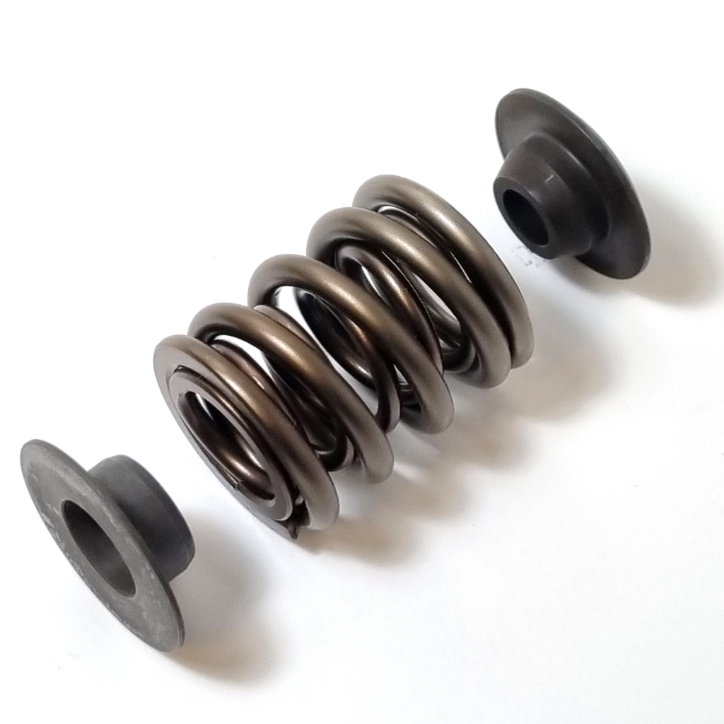
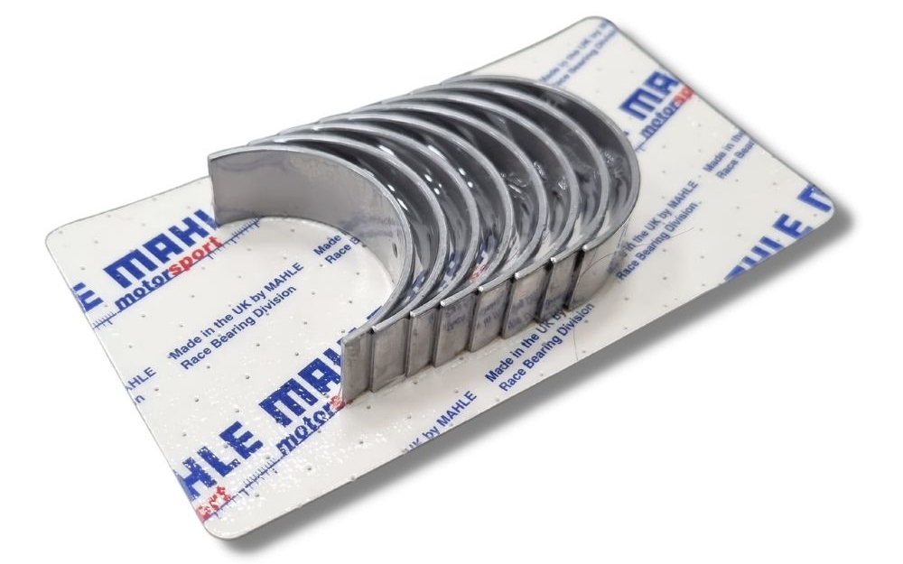
Selecting the correct material for a con rod bearing is vital if the bearing is to survive the harsh dynamic pressures present in the lubricant film. You can read more about the materials and coatings that a modern crank bearing utilises here.
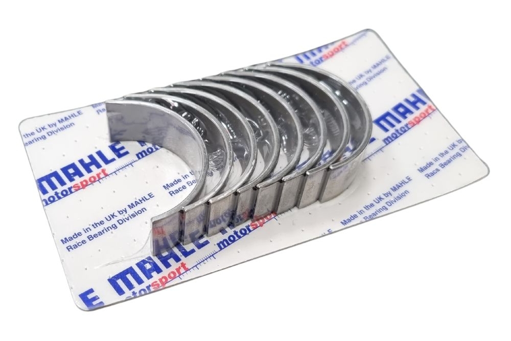
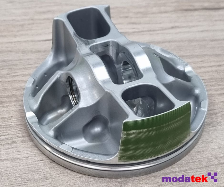
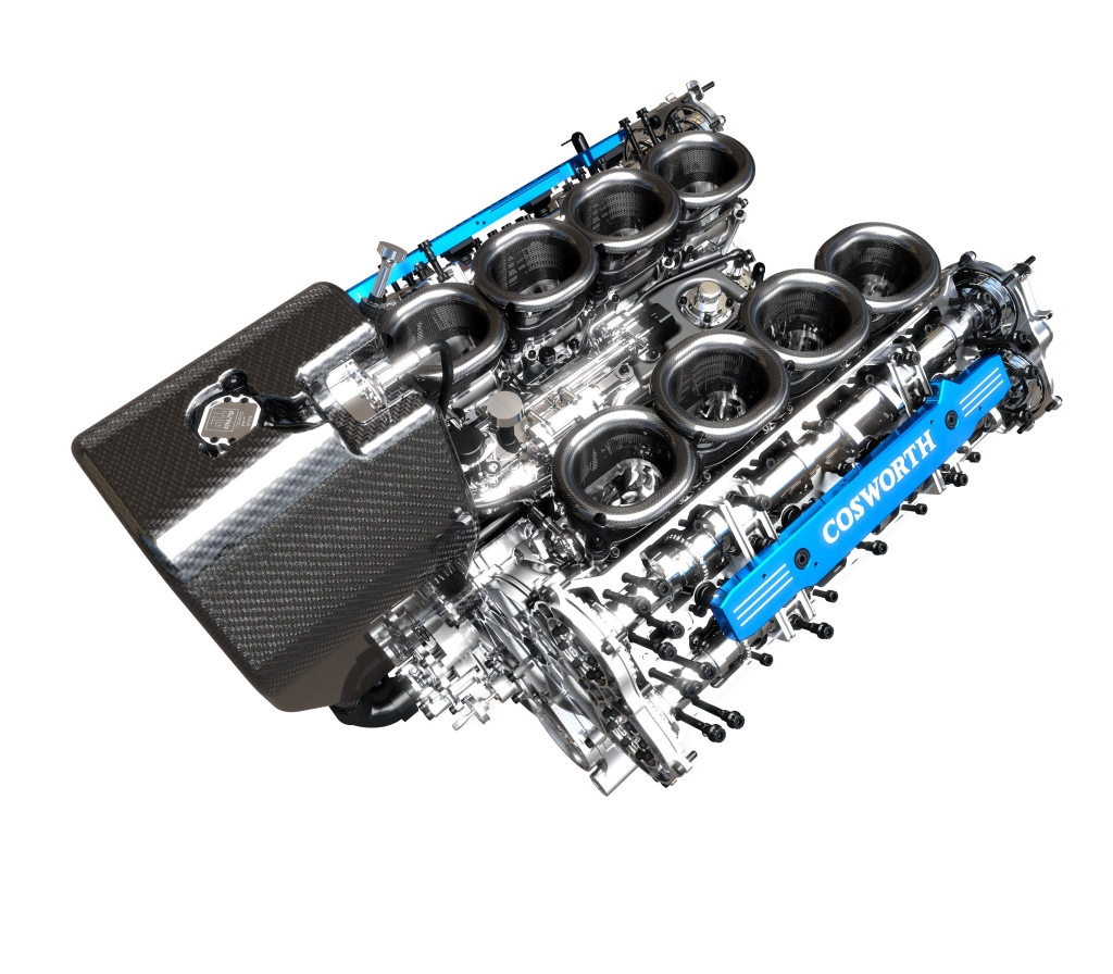
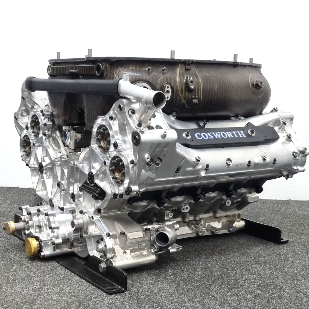
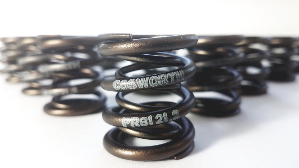
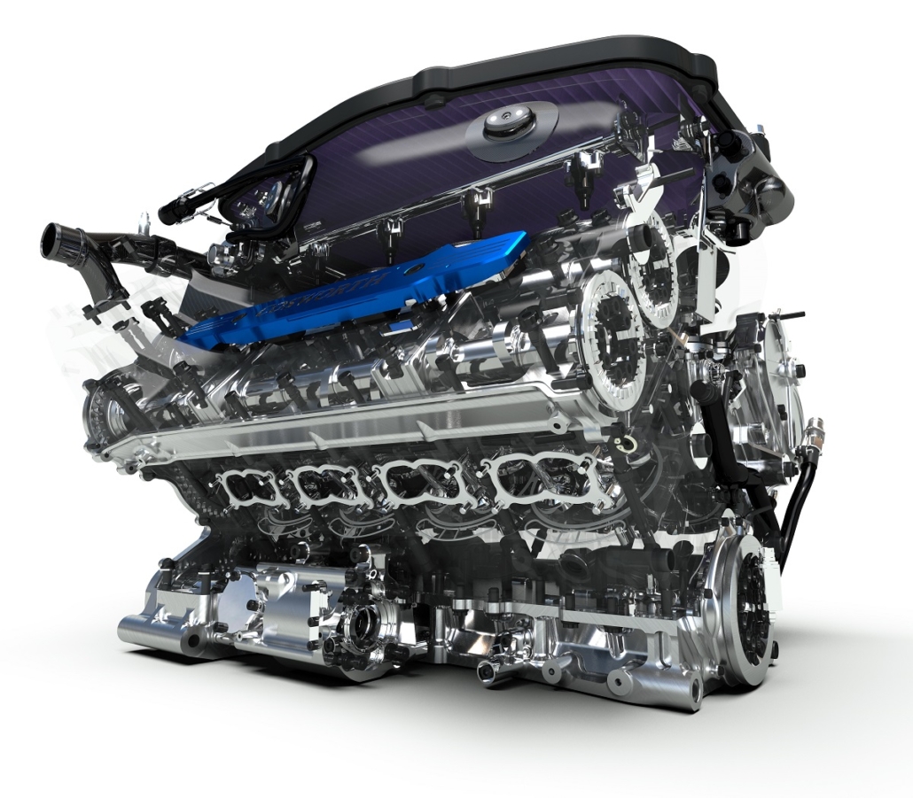
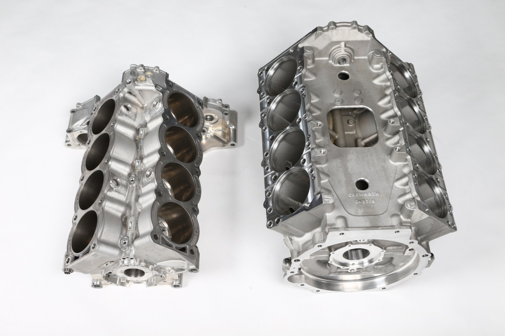
Modatek supply a variety of crank bearings for a range of Cosworth engines, such as rod bearings for the YB engine and main journal bearings for the DFV. If you need crank bearings for your Cosworth engine then get in touch.
This feature on crank bearing lubrication is based on an article written by Modatek’s Matt Grant for Race Engine Technology, issue 114. You can purchase a back copy of this publication here: https://www.highpowermedia.com/Product/race-engine-technology-issue-114