VALVE HEAD GEOMETRY
The geometry of the head of an inlet or exhaust valve is all about engineering compromises. One compromise is that the head has to be as light as as possible and yet also be as strong as possible. Another compromise is that the head has to seal off the combustion chamber when closed and yet also provide minimal restriction to gas flow when open. And all of this has to be achieved while the valve is subject to extremely high operating temperatures and loads.
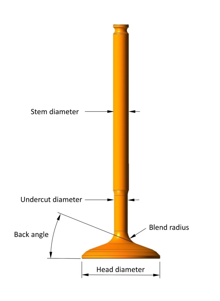
Most valve designs begin life with just the basic dimensions of valve head diameter, stem diameter and stem length. The valve head diameter is usually a function of the cylinder bore size, and is maximised as much as possible for two reasons: increased gas flow plus a larger seating area for the valve head (hence a lower seating pressure).
Valve Head Design Terms
Once the basic geometry of the valve has been decided, the designer must then focus on the more detailed area of the stem radius and the profile of the back of the valve head, both of which are of utmost importance to maximise the strength of the valve and minimise the blockage in the gas flow.

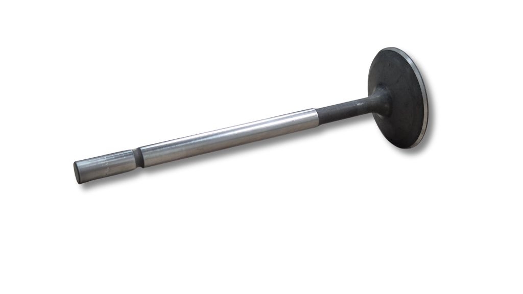
As shown above, working down the stem towards the valve head, there is usually an undercut diameter so that the stem grinding wheel doesn’t foul on the back of the valve head. The surface finish and cylindricity of the stem is vital to ensure that the stem seal functions correctly, so the stem needs to be ground and sometimes polished.
A continuous blend radius then joins the undercut diameter (if present) or the stem diameter to the conical straight section of the back profile. The back angle is defined as the angle between this straight profile and the face of the valve head. Some valves have a large convex radius instead of a straight back angle.

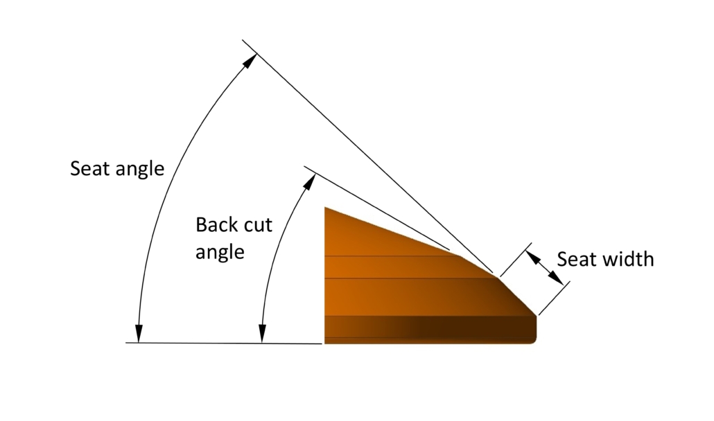
We then come to the seat angle, the conical face that contacts the valve seat in the cylinder head, which is usually in the region of 45° to the face of the valve. The width (and therefore area) of the seat face is kept as small as possible to maximise gas flow, but large enough to withstand the compressive stresses that the landing valve will impose. It is sometimes preceded by a small straight segment called the back cut angle, commonly at 30° to the face of the valve, which helps to lessen the transition between the back angle and the seat angle.
Finally we come to the small radius between the outer diameter of the valve head to the valve face, which is often overlooked but can play a pivotal role in the flow of gases around the valve head.
So, the design of the valve head is far from simple. Undercut diameter, blend radius and back angle must all be carefully chosen, and all three parameters are a compromise between strength and gas flow. In general, stresses are reduced with larger stem diameters and blend radii, to the detriment of gas flow. A steeper back angle normally results in better flow but increases the mass of the head significantly, increasing stresses higher up.
Turbulence
Given that the head of the valve will always be obstructing the gas flow, valve designers have been busy over the years with finding ways to minimise the blockage from the valve head, and in the case of the inlet valve even exploit the presence of the profiled back of the valve head, ultimately to improve combustion.
Combustion efficiency depends on what are colloquially called the three Ts – time, temperature and turbulence. For reasons that are beyond the scope of this article, the amount of turbulence in the combustion chamber has proved to be critical to increasing flame velocities to achieve a good propagation of the flame front.
With a flow rate of more than 75 m/s past the inlet valve in some race engines, all inlet valves will generate an element of turbulence. The type of turbulence depends on the number of valves per cylinder, creating either a swirl type of turbulence or a tumbling type. In truth, both swirl and tumble turbulences are sought, although some engine designs favour one over the other.
Intuitively, it would make sense for the transition between the various segments of the profile to be as smooth as possible. In reality though, many inlet valve designs incorporate sharp edges to break up the gas flow and promote turbulence.
Sharp Edge Step
Going one step further, some the heads of some inlet valves also include a raised (but very shallow) circular step or lip with a sharp edge to disrupt the gas flow, just ahead of the seat face.

The lip doesn’t need to be very high at all to ‘trip’ the gas flow as it enters the combustion chamber. The turbulence created has been found to assist the flow of the gas around the corner of the valve head and across the face of the valve.
Shallowing the back angle of the valve head results in a lower mass, and this is taken to the extreme when the valve head begins to resemble a disc. In such cases the lip has been reported to be of benefit because it can create a circulating turbulent area ahead of the lip in the blend radius, lessening the effect of the shallow back angle.
Whatever the reasons for its presence, the lip needs to have an extremely sharp corner, and perhaps one reason why this feature isn’t seen in roadcars is because carbon build-up over time will fill the corner of the lip, diminishing the influence of the edge. Also, the lip is often angled towards the blend radius, making mass-production machining extremely difficult.
Swirl Polishing
A number of valve manufacturers finish the blend radius between the valve head and stem with a detailed polishing operation, commonly known as swirl polishing. As the name suggests, this creates a polished surface with very fine marks spiralling outwards. Traditionally this has been done by hand but now manufacturers are starting to use CNC machines to replicate the swirl polishing, resulting in a more consistent process.
The polishing removes any excess forging material or machining marks, both of which will act as stress raisers that can drastically weaken the valve. Another reason put forward for swirl polishing is that the spiralling marks will create a vortex effect in the gas flow, leading to turbulence. Although the gains in gas flow might be small, the effect of removing raised material from the blend radius can only assist with better gas flow.
Undercut
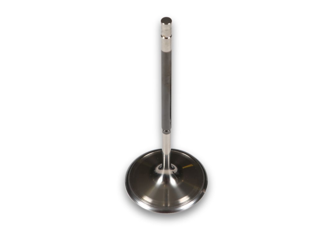
Another method for improving gas flow past the valve is to reduce the diameter of the stem just above the blend radius (like on our DFV inlet valve pictured below). As mentioned, it is common to have an undercut diameter here anyway so that the stem diameter can be ground.

A reduced undercut diameter will make it easier for air to flow down the port onto the back of the valve (in the case of the inlet valve) and to flow off of the back of the valve and up the port (in the case of the exhaust valve). Combining an undercut diameter with swirl polishing to an existing valve is reported to give an instant improvement in airflow tests.
Hollow Valves
Hollow valves offer two significant advantages – mass reduction and heat dissipation. Some valves have a cylindrical bore in just the stem, whereas others have the hollow cavity extend into the head – usually, the latter is only possible to create by forging.
If the mass of the valve can be reduced then there is a corresponding reduction in the reciprocating forces needed to move and stop the valve. The forces to move the valve are provided by the cam lobe pushing the valve down and by the valve spring pulling the valve back up. The valve seats have to provide a reactionary force to stop the valve moving upwards.
So, if we can reduce the valve mass, this can potentially lower the cam lobe pressure, lessen the spring forces (and hence, in the case of wire springs, minimise the stress in the coils) and decrease the valve seat pressures. Lower pressure at the cam lobe means less friction too, thereby aiding the reduction of wear in the lobe and follower surfaces. Or, as most race engine designers would prefer, the opportunity to run at faster speeds and with more aggressive cam profiles for improved performance.
The second advantage of hollow valves is that the internal cavity can be partially filled with a cooling agent, such as sodium or sodium potassium. The benefit of increased valve cooling has become more prevalent with the move to small-displacement turbocharged engines. Even worse for valve temperatures, turbo boost levels have risen, resulting in more heat being transferred to the valves.
Exhaust valves in particular have suffered with ever-increasing temperatures, but the switch to coolants inside hollow valves reduces the operating temperatures and opens up the possibilities of running hotter exhaust gases or using materials that might otherwise have failed at high temperatures, such as titanium.
Exhaust valves will transfer heat to the cylinder head through seat contact, but sometimes the materials chosen for valves and seats end up having low thermal conductivity, which is another reason for implementing cooled hollow valves. The coolant in a hollow valve can move heat up the stem of the valve and reduce the amount of heat transferred across to the seat.
Hollow valves are normally only partially filled with molten coolant, allowing the coolant to slosh up and down the valve as the valve reciprocates. Somewhat fortuitously, the coolant is at the bottom of the valve when the valve is pushed open and the valve head is hottest, and it then moves to the top of the stem when the valve is stopped suddenly by the seat and closes, transferring heat to the surrounding valve guide.
Sodium is very good material to use as it solid at room temperature and so can be squeezed into the open hole in the valve. Once the valve temperature approaches 100 °C the sodium will melt and move inside the valve in the manner described above. It has the added benefit over alternative coolants because it has a relatively high boiling point, of 883 °C, which makes it suitable for most exhaust valve applications.
This feature on valves is based on an article written by Modatek’s Matt Grant for Race Engine Technology, issue 103. You can purchase a back copy of this publication here: https://www.highpowermedia.com/Product/race-engine-technology-issue-103


