THE HIDDEN SECRETS OF A FORMULA 1 PISTON
There’s more to a Formula 1 piston than first meets the eye. The last of the V8 naturally aspirated engines from 2013 were built with pistons that contained lots of technical secrets. Let’s take a closer look at what some people call an engineering work of art – the Cosworth CA2010 Formula 1 piston.
(By the way, we still have some race-used pistons available to buy from our on-line shop.)
The Cosworth CA2010 Formula 1 Engine
The Cosworth CA2010 engine was a development of the CA, an engine which was designed and built for the 2006 season for use by Williams. As there were no restrictions on engine speed back then, peak speed was pushed to the limit and the CA was capable of reaching 20,000 rpm, making it the fastest engine on the grid.
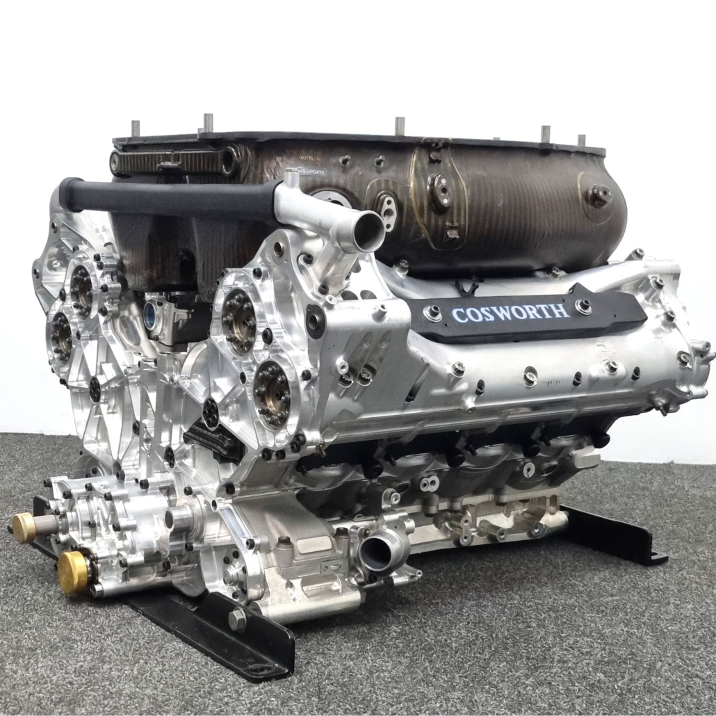
Sadly Cosworth were forced out of Formula 1 at the end of 2006, but four years later were back with the CA2010, powering Williams again alongside the three new teams, Virgin Racing, Lotus Racing and Hispania Racing. By now the rules mandated a maximum speed of 18,000 rpm, but engine life had increased almost threefold, so there was no let up in the pursuit of reliability.
Formula 1 Piston Mass
One of the most stressed parts in the engine was the piston, and it’s not hard to see why. At a speed of 20,000 rpm the piston was subjected to accelerations of over 10,000 G (that’s not a typo, that’s ten thousand G!). If you paid attention to your high school physics lessons then you’ll remember that force is mass multiplied by acceleration, so reducing piston mass was a critical step to reducing the forces that the piston was exposed to.
The piston design represented the culmination of years of hard work to reduce mass, and the CA2010 piston hit the scales at just 215 g. Considering that the material had to be an aluminium alloy as mandated by the F1 technical regulations, this was a remarkable achievement.
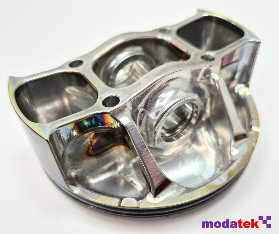
Undercrown Shape
A lot of the weight saving came from the unique shape of the piston. Alex Hitzinger, who was the chief engineer in charge of the design of the CA engine, recently commented on how the undercrown shape of the piston evolved. “We came up with this design philosophy (dog bone shapes, extremely stiff, hollow structures) through a design study we did for a very thin walled investment cast titanium piston. We never made one, because titanium got banned as a piston material before we could try it, but we learned a lot through that exercise and the result was the a piston that was capable of revving to 20,000 rpm.”
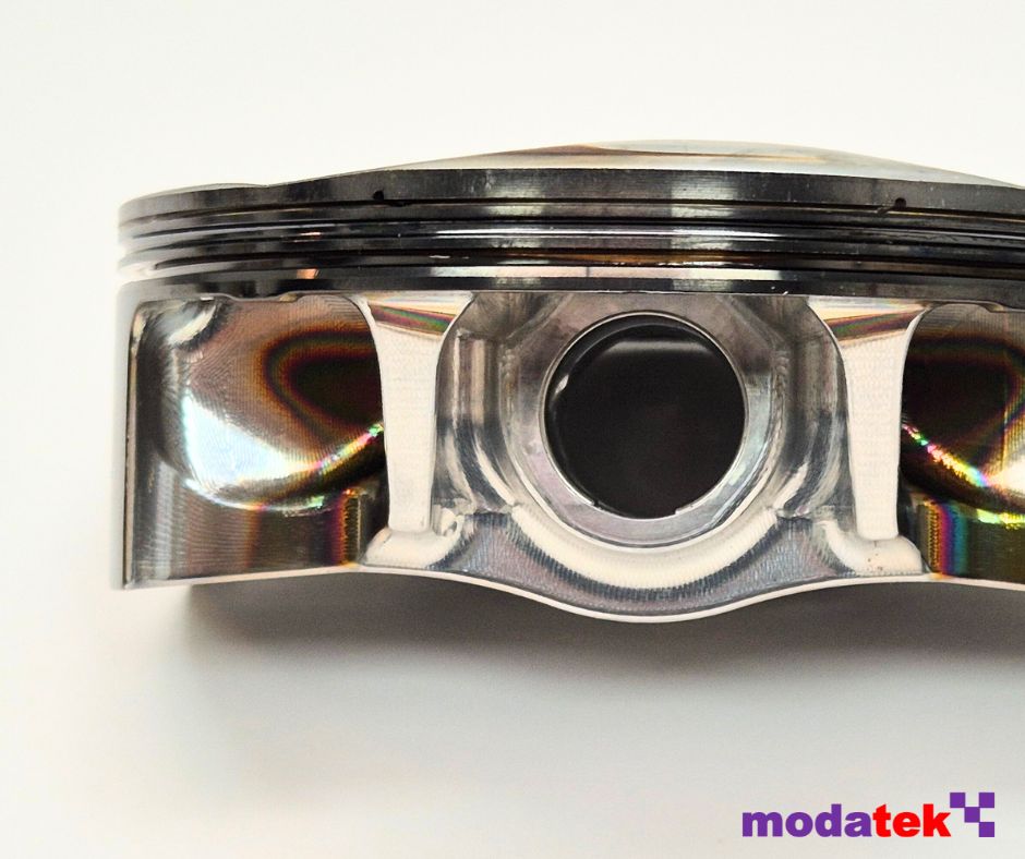
Looking at the undercrown, the shape looked like a fairly conventional boxed and bridged design. However, there were a number of clever design features that were optimised through an extensive period of FEA (finite element analysis).
One of these features was the vertical drillings at each corner of the central box section that carried the pin bores. These drillings were actually slightly angled inwards, and were there purely for mass reduction.
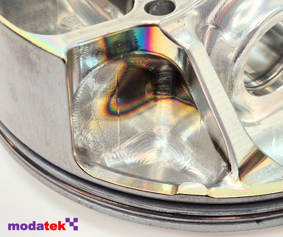
The area underneath the buttresses was waisted down, and there was no material underneath the spars of the box section. These features couldn’t be generated from forging and so have had to be machined out. In fact, the entire undercrown had to be extensively machined to remove any surface defects that might have been left over from the forging process.
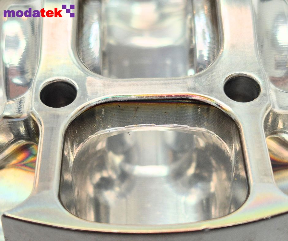
Crown Shape
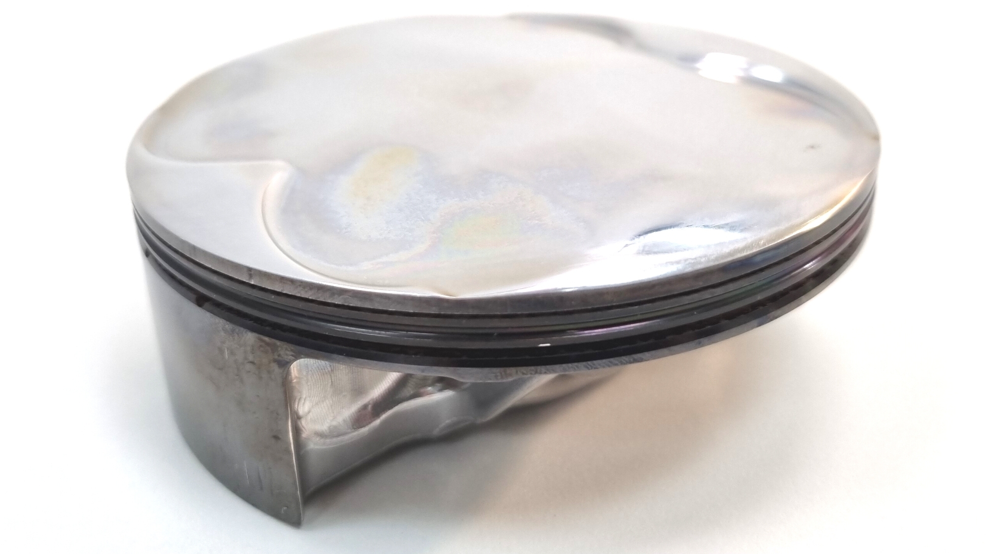
The design of the crown was carefully shaped to match the corresponding geometry of the combustion chamber in the cylinder head. The crown shape consisted of a diamond-shaped central flat section which actually wasn’t flat. Although difficult to see in photos, the crown of the piston was very slightly domed, which at TDC created a small flat bowl into which the spark plug would initiate the combustion of the air and fuel mixture.
The crown included a pair of very shallow pockets for clearance to the inlet valves and another pair for the exhaust valves. Any sharp edges had to be carefully blended away to reduce the chances of pre-ignition.
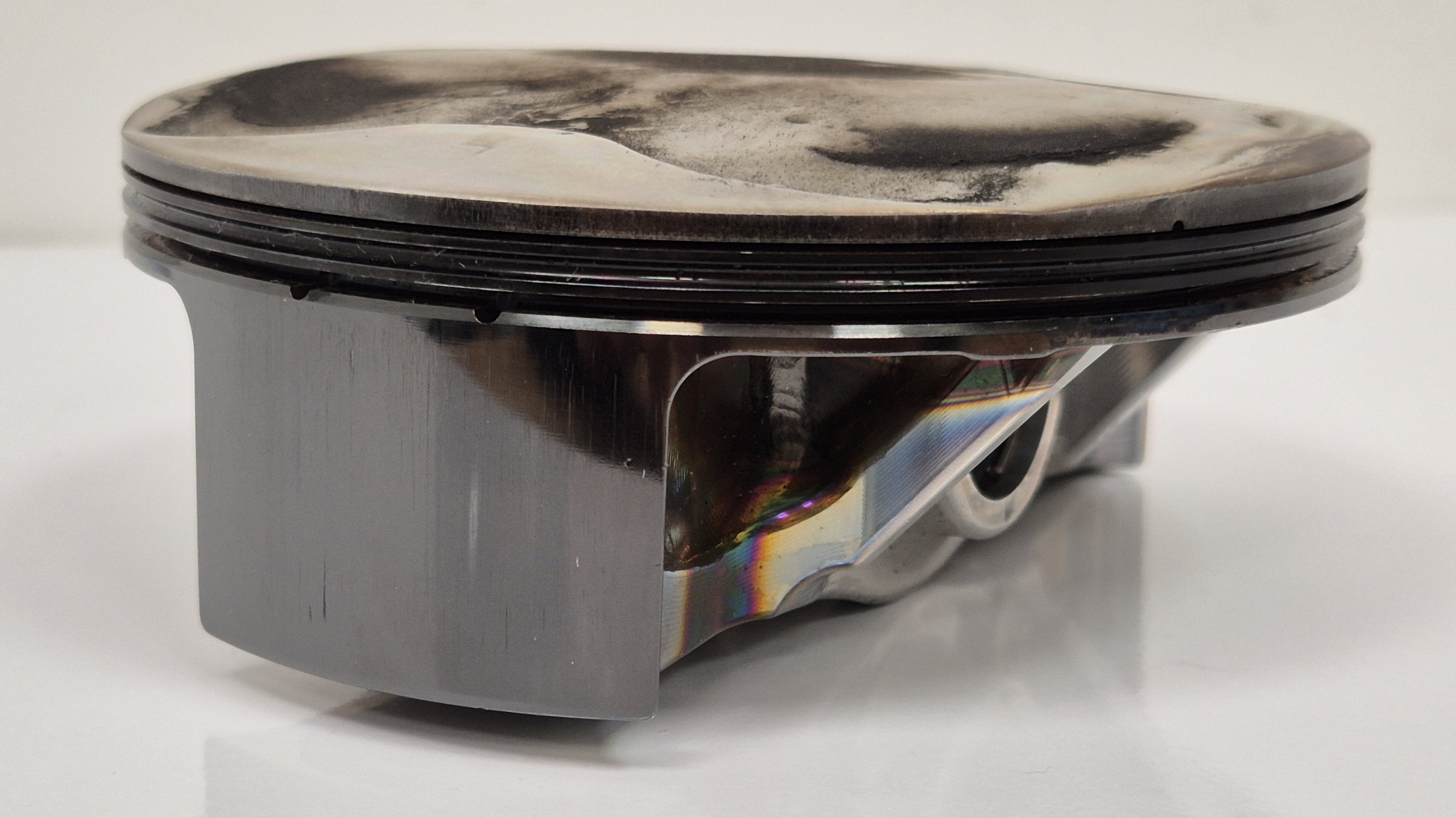
One of the obstacles that had to be overcome was stopping the crown from melting, hence each piston was cooled by six oil squirt jets. The contact with hot oil resulted in the staining that could be seen on the undercrown after extended periods of running.
Ring Grooves
One of the most notable features of the piston was the tight packaging of the ring grooves, which were moved upwards as much as possible. Like most F1 pistons of this era, the sealing of the cylinder bore wall was accomplished with just one compression ring along with an oil control ring.
The height of the compression ring groove was incredibly small at just over 0.63mm. Inside this groove were small horizontal ports that fed combustion gas into the back of the groove and thus helped force the ring out towards the bore.
Likewise, the oil control ring groove was also very narrow at 1.5 mm height, and it contained ports that allowed oil to drain from within the groove to the underside of the piston. Between the two ring grooves was what’s known as an accumulator groove. This was a vee shaped groove that created a volume of gas below the compression ring. This then helped to maintain the differential pressure across the ring that was required for effective sealing.
Skirt
The skirt of the piston was very short, just enough to minimise rocking of the piston in the bore. The coating on the skirt was DLC (diamond like carbon), which had been introduced in 2004 on the forerunner to the CA engine, the TJ. Cosworth estimated that the coating was worth around 4 bhp on the TJ, thanks to the coating’s ability to reduce friction.
The skirt of the piston was very short, just enough to minimise rocking of the piston in the bore. The coating on the skirt was DLC (diamond like carbon), which had been introduced in 2004 on the forerunner to the CA engine, the TJ. Cosworth estimated that the coating was worth around 4 bhp on the TJ, thanks to the coating’s ability to reduce friction.
The profile of the skirt was a complex shape that featured both barreling and ovality. This shape had been optimised through FEA and dyno testing to ensure that the skirt matched the shape of the cylinder bore when the piston was distorted from loading and thermal expansion.
Don’t forget, You can get hold of one of these pistons along with the connecting rod from the Memorabilia section of our on-line shop.
We’ve taken some of these details from an excellent article written by Ian Bamsey in Race Engine Technology issue 073. You can purchase a back copy of this publication here.
We are Cosworth’s official distributor for their historic engine parts, and we supply a wide range of parts for a number of different Cosworth historic engines, from BD, YB and DFV through to the more recent F1 engines like the CK, TJ and CA. Our mission is to help our customers build better engines by supplying high quality parts backed up with a design consultancy that utilises over 25 years experience in top level motorsport.

