PNEUMATIC VALVE SPRING SECRETS REVEALED
In our latest technical blog we take a closer look at pneumatic valve springs. They’ve been on Formula 1 engines for the last 30 years, but how do they work and why aren’t they in our road car engines?
Have you ever watched a Grand Prix and watched on in dismay as your favourite driver’s pit stop seemed to last for an eternity. Worst still, mechanics seemed to be stood around the car doing nothing, with the exception of one mechanic who is frantically trying to connect up an air hose to the side of the car.

Chances are that the engine of your favourite driver is currently suffering from what normally turns out to be a terminal failure of the pneumatic valvetrain system. The hapless mechanic will be trying to add air or nitrogen to the system to counteract a leakage somewhere deep within the engine.
So what is a pneumatic valve spring and is it really better than a conventional wire valve spring? Well, in a nutshell, a pneumatic valve spring is basically a cylinder of pressurised gas (air or nitrogen) which behaves in a similar manner to a wire spring by creating an upwards force on the inlet and exhaust valves.
All Formula 1 engines run some sort of pneumatic valvetrain and pneumatic valve springs are common on a few other premier motorsport categories like Moto GP. It goes by a number of different names – some engine manufacturers refer to it as the PVRS (pneumatic valve return system) or AVS (air valve spring), but they all work in roughly the same way.
Pneumatic valve springs were pioneered by Renault for its Formula One engine back in the later 1980s, and have long since been adopted by all the other manufacturers in Formula One. Cosworth switched to its own system in the early 1990s – remember the fuss when it supplied engines that were upgraded with pneumatic valve springs to Benetton and not McLaren, resulting in a frustrated Ayrton Senna?
Pneumatic Valve Spring Components
In a pneumatic valve spring air or nitrogen is fed into drillings in the cylinder head at a regulated pressure of (typically between 10 and 20 bar, depending on several parameters such as the volume of the body and the mass of the valve) from a supply bottle mounted externally on the chassis or from a compressor, and then introduced into the pneumatic valve body through a non-return valve.
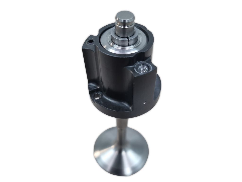
Inside the body, the gas will be compressed to more than 80 bar as it is squashed by movement of a disc secured to the valve with cotters, called the reciprocating seal carrier. Around the outside of this carrier is a seal that runs inside a honed bore inside the body (sometimes the bore is in a separate sleeve that is inserted into the body). At the base of the body is another seal carrier which houses the stem seal.
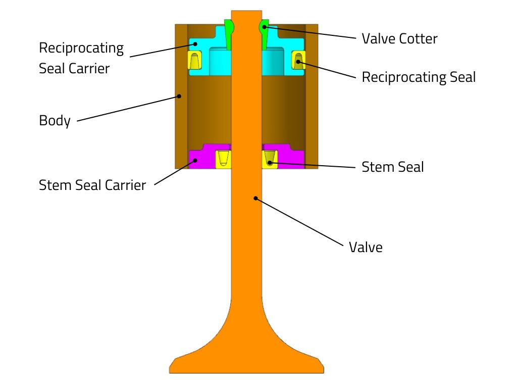
Both seals are usually energised by a combination of the internal gas pressures in the body and metal garter springs which forces the seals out even when there are lower gas pressures present.
The exact construction and materials that are used to manufacture the seals remains a closely guarded secret between the seal manufacturers and the engine manufacturers. This is even true on the seals that we supply to customers rebuilding historic Formula 1 engines.
If you want to see some pneumatic valve spring components up close then take a look at Brian Garvey’s excellent tear-down.
Controlling Oil
Both the reciprocating seal and the stem seal will be required to maintain a perfect seal whilst running at phenomenal speeds. It is imperative that the surfaces aren’t dry, otherwise the seals will overheat. The running surfaces of both seals have to be lubricated with oil, but the introduction of oil has to be carefully controlled.
Thankfully, in the environment that the pneumatic valve springs find themselves in, there is plenty of oil around. In the valvetrain chest, which is the space around the pneumatic valve bodies, there is always a mist of oil present. This oil finds it way onto the walls of the bores in each body, and can then lubricate the reciprocating seal.
The reciprocating seal has a shallow groove running around the middle that fills with oil, and when the seal moves the pressure in the groove increases until it reaches a point where the oil is forced into the body. Once in the body, the oil can then lubricate the static stem seal.
But too much oil in the body can be catastrophic. Unlike gas, oil is virtually incompressible. If too much oil gets into the body of a pneumatic valve spring then it will hydraulically ‘lock up’. This in turn results in massive forces on the seals and carriers, which can lead to catastrophic engine failure.
The amount of oil present can be maintained by using small pressure relief valves (PRV), which will open when too much oil is present, and if located correctly they will vent the oil out of the body. The operation of these valves is similar to the much larger PRV that are found next to the oil pressure pump.
Normally each pneumatic valve body will contain its own miniaturised PRV. The PRV consists of a tiny ball bearing which is pressed by a spring against a conical face to seal off the oilway. When the pressure in the body reaches a certain level the spring force is overcome and the ball moves, opening up the oilway. The installed length of the spring is carefully preset with a graded-length screw, which is selected during build to ensure that the PRV opens at the right pressure.
So, when the amount of oil present in the body gets too much, the pressure in the body opens up the PRV and the oil escapes out. However, it’s not always as simple as this. Sometimes gas will escape with the oil, depleting gas from the body, and so more gas will be required. Effectively, the body has to take a gulp of gas from the supply source.
If this occurs repeatedly or if the seals start to leak then the gas bottle will soon be exhausted and will have to be topped up, which brings us back to the lengthy pit stop, frustrated driver and exacerbated mechanic.
Normally this leakage doesn’t just go away, and if there isn’t enough replacement gas added during the pit stop then eventually the bottle will run out. In Formula 1 the emphasis is on saving engines for future use, so the team will normally elect to retire the car rather than risk a loss of valve control and ultimately engine failure.
Pressure Regulator
One important component in the pneumatic valvetrain is the pressure regulator. This device is spring-loaded and can be set to ensure that the supply of the gas going into the engine is at a consistent pressure regardless of the pressure of gas in the bottle.
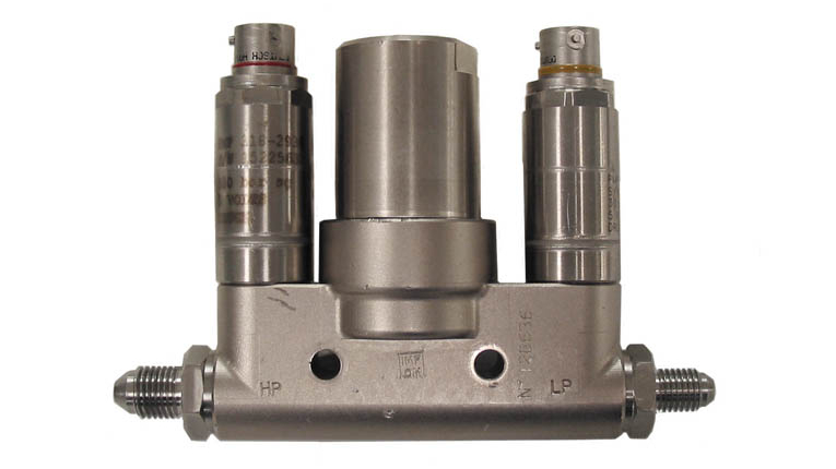
The pressure regulator on a race car is a more complicated version of one that might be found on a diving bottle. It’s normally mounted in a cavity in the sidepod, and as such is subjected to extreme vibrations and temperatures.
This regulator also typically has two pressure sensors installed – one will read the pressure from the bottle, and the other will record the pressure going into the engine. A deteriorating bottle pressure is a sure sign that the engine is consuming gas.
The Benefits of Pneumatic Valve Springs
Thanks to its ability to be able to cope with higher loads, a pneumatic valve spring offers two significant benefits over a wire spring. First of all, most wire sprung engines are limited to around 12,000 rpm because of the strength of the springs. If you want to go past that speed then you’ll probably have to switch to a pneumatic valve spring.
Secondly, most race engine designers want a profile that will give rapid opening of the valve, followed by the required duration of opening and then a rapid closing of the valve. Again, wire springs can be a limiting factor for the aggressiveness of the cam profile. If you want to run aggressive cam profiles then you’ll probably benefit from a pneumatic valve spring.
So how is a pneumatic valve spring superior to a wire spring? An esteemed engineer by the name a of Professor Gordon Blair wrote a series of articles for Race Engine Technology that examined valve springs in great detail.
In one of these articles (“Steel Coils Versus Gas”, RET 23) he included an in-depth comparison between a single-coil steel spring and a nitrogen-filled pneumatic valve spring. He analysed the amount of valve bounce from both systems and surmised that the valve control with a pneumatic spring was superior to that provided by the steel spring.
He highlighted several reasons for this improvement in valve control. First, the mass of the reciprocating seal and carrier was only around one-fifth of that of the steel spring. Also, the gas spring displays an inherent damping behaviour thanks to the hysteresis of the gas. And perhaps most important, unlike helical wire springs, pneumatic valve springs cannot suffer from surge problems.
Will We See Pneumatic Valve Springs on the Road?
The simple answer to this question is no. For a start, most road engines don’t need to run at the speeds seen in Formula 1. Moreover, most road engines don’t need to use aggressive cam profiles. So a conventional wire compression spring can do the job and there are plenty of metallurgical advances that make a wire spring incredibly robust.
The other problem is that, despite 30 years of research, pneumatic valve springs are still relatively unreliable, certainly when compared to a wire spring. There is an incredible amount of care and attention that is required when assembling a pneumatic valve spring. Just the slightest amount of dirt or debris can cause the seals to leak. In the OEM world of mass-production, it would be extremely difficult to assemble pneumatic valve springs on a production line within a sterile environment.
So it’s highly unlikely that you’ll ever see a warning sign flash up on your dashboard whilst you’re driving to the shops telling you that you need to come in for an unscheduled pit stop for a bottle top up.
Modatek can supply parts and consultancy to customers who want to rebuild the pneumatic valve springs in their historic engines. Get in touch to find out how we can help.
 Pathompong Thongsan from Dreamstime
Leave a Reply
Want to join the discussion?Feel free to contribute!