OIL PUMP TECH
At the heart of an engine’s lubrication system is the oil pump, which has to continuously move oil around the complex maze of passageways inside the engine. A correctly working oil pump is vital for engine health – just one instantaneous drop in oil pressure could be catastrophic for the lubrication of bearings. But how do oil pumps work, and what are the different types of pumps that can be used on race engines?
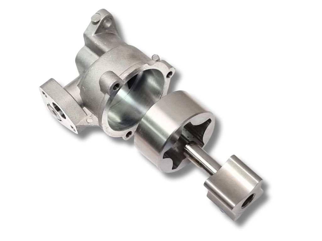
The pump moves the lubrication fluid by trapping the fluid between moving elements. Irrespective of the type of pumping elements used, these pumps are commonly referred to as positive-displacement pumps. In a positive-displacement pump, the internal elements move to create an open void that expands and fills with the fluid. The elements then move, taking the fluid with them, after which the elements compress the volume of fluid, forcing it out of the pump.
Positive-displacement pumps can be broken down into two groups: rotating and reciprocating. The vast majority of oil pumps we find on race engines tend to be of the rotating variety, as the rotating action of the elements gives a relatively smooth flow of oil and can be designed to be compact and light. Rotary drive can be provided directly from the crankshaft via a gear, belt or chain, making them easy to package into either a new clean-sheet engine design or onto an existing engine’s architecture.
Internal Gear Pumps
The anatomy of an internal gear pump is relatively simple – an inner gear with external teeth runs inside an outer gear with internal teeth. The outer gear is housed in a cylindrical body with inlet and outlet ports on the end. The inner gear will typically have one tooth fewer than the outer gear, and the two gears run on fixed eccentric axis. When the two gears rotate, the volume created between the meshing teeth will expand and contract to pump the fluid.
Internal gear pumps include a crescent shape in the void under the inner gear. This crescent will divide the two rotors and act as a seal between the high- and low-pressure areas.
Gerotor Pumps
A sub-set of internal gear pumps is the gerotor pump, short for generated rotor. The gerotor design does away with the crescent, creating a compact and simple solution, like our Cosworth YB oil pump.
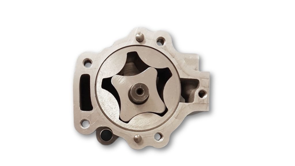
With only two moving parts, gerotor pumps are a simple and versatile product, and it’s easy to see why they have been so popular over the years in road as well as race engines. Gerotor pumps are especially common as oil pressure pumps, as they can have a lower fluctuation in output pressure when compared with an external gear pump.
Another plus point for the gerotor design is that the housing needs only one cylindrical bore machining in it to accommodate the outer gear, unlike an external gear or lobe pump which needs two rotor bores. And the packaging of one gear inside another means the overall size of a gerotor pump can be quite small compared with other pump options.
One other advantage that the gerotor pump has over other types is thanks to the design of the rotor teeth. These can have extremely tight clearances, which leads to less leakage between the teeth and hence better efficiency.
Note though that the tight clearances can also be detrimental, as the rotors are more prone to damage from debris. That makes gerotor pumps less attractive for scavenge pumps, where debris in the oil scavenged from crankcase is more prevalent.
Surface wear on the teeth of gerotor pumps can also be less than that seen on those of external gear pumps. That is because the relative velocity between the inner and outer gears is quite low. Take for example a gerotor pump with five teeth in the outer rotor and four in the inner rotor. At a pump speed of 2,000 rpm the relative rotational speed between the inner and outer rotors will be only 400 rpm.
Trochoid Gear Profiles
The devil is of course in the detail, and in the design of the gear profiles this maxim is especially true. Most gear profiles in internal gear pumps are from the family of trochoid curves, which is the path created by a fixed point on a circle rolling along a straight line.
A dissection of the mathematical formulae used to generate a member of the trochoid curve group is beyond the scope of this blog, but we can touch on the definition of some of the types of trochoid curves and look at a few of the different gear profiles used by manufacturers for their ranges of gerotor pumps.
The term ‘trochoid’ actually covers a number of different subsets of curves, including epitrochoids and hypotrochoids. An epitrochoid curve is formed by the movement of a fixed point on one circle rolling around the outside of another circle. By contrast, a hypotrochoid curve is created by rolling one circle around the inside of another.
If you’ve ever played with a Spirograph toy then you will remember the motion of a pen pushed through a hole in the small cog as it rotates inside or outside a larger toothed disc. These curves are actually epitrochoids and hypotrochoids.
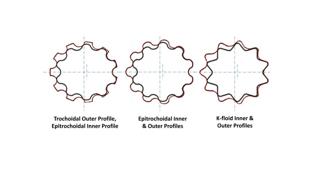
In a standard trochoid profile gear set, the inner gear is epitrochoidal but the outer gear isn’t and hence the profiles of the inner and outer gear teeth don’t mesh perfectly. As a result, standard trochoid profile gear sets can tend to have lower sealing properties (some of the oil from the high-pressure side will escape back to the low-pressure side) when compared with other gear profiles, giving rise to a lower volumetric efficiency.
A true epitrochoidal gear set has epitrochoidal profiles on both the inner and outer gears, and the profiles will fit perfectly inside one another when they mesh. This variant will provide a good compromise between volumetric efficiency and resistance to wear. Conversely, this style of profile can be the most prone to damage from debris, as there are no gaps for the foreign material to reside in when it passes through the teeth.
Hypertrochoid curves aren’t normally used to construct the gear profiles on automotive internal gear pumps. That is mainly because such profiles can create abrupt intersections between the lobes, which can lead to premature wear. The sharp faces of the inner gear can quickly damage the lobes of the outer once they are subject to the high speeds seen in a race engine oil pump.
One other profile used in gerotor pumps is termed the K-floid, which is essentially a hypotrochoid curve and an epitrochoid curve stitched together. K-floid gear profiles are reputed to offer good resistance to debris, but they can end up with low volumetric efficiency and are more vulnerable to wear when compared with other profiles.
The most prevalent gear profiles on the market are generated from trochoid curves with epitrochoidal inner gears or matched epitrochoidal inner and outer gears.
Some gerotor pumps also feature an asymmetric tooth profile on the outer gear. This can make then more efficient, but the downside is that the root radius tends to be smaller, leading to large stress concentrations, making them less suitable for high-performance applications.
Tooth Factors
Aside from the tooth profile, there are other changes in geometry that can be altered to increase or decrease flow. The amount of eccentricity will have a knock-on effect on the tooth length, and can weaken the gear. If the eccentricity is changed then the lobe radius of the outer diameter must also be changed to reduce the stress in the lobe.
The number of teeth chosen will have a major impact on pump performance. Fewer teeth mean that the overall diameter of the pump can be smaller, which in turn makes it easier to package in the engine. Fewer teeth also result in a reduction in power loss for a given flow rate, but the downside is that they have to run at a higher rotational speed, which can increase wear.
On the other hand, more teeth will give fewer pressure fluctuations and hence a smoother overall oil pressure. The fluctuation is sometimes referred to as pressure or flow ripple, and is an unwanted side-effect of any positive-displacement pump. The effect of pressure ripple is mechanical vibration in the oil circuit in the engine, which can damage components such as oil hoses, seals, and bearings, so any measures that can minimise pressure ripple are likely to be of great benefit.
External Gear Pumps
External gear pumps consist of two gears laid side by side, with one gear driving the other. The movement of the oil by an external gear pump is similar to that for an internal gear pump, and like the internal gear pump it is the teeth on one gear that drives the teeth on the other.
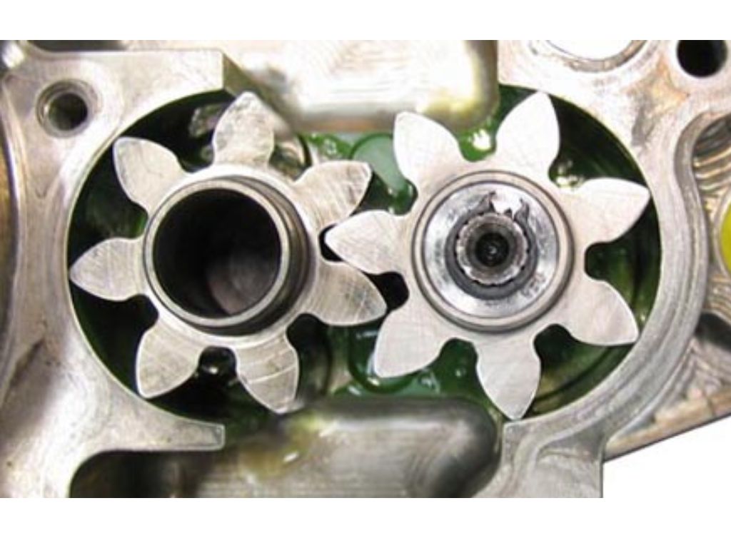
When the gear teeth come out of mesh they create an expanding volume that is filled by the oil fed from an inlet port. This oil is trapped in the gap between the teeth and the inner diameter of the housing, and as the gear rotates then so too does the oil. The gear teeth then come back into mesh, collapsing the volume of oil and forcing it into the outlet port and out of the pump. Most race engine oil pumps contain spur gears with parallel teeth, but in other applications the gears can be angled in a chevron pattern.
The tooth profile for an external gear pump is different from that used for an internal gear pump. Most external gear pumps contain gears with involute tooth profiles. An involute curve is the spiralling path created by unwinding an imaginary taut string from a stationary circle. The curve is prescribed by a number of inputs, including module, pressure angle, addendum modification coefficient and base circle diameter. All these variables can be adjusted to give the final tooth shape.
External gear pumps will typically have supporting journal shafts at either end of the rotors (as do internal gear and external lobe pumps for that matter), and the shafts run inside bearings or bores in the pump housings and cover. Because the shafts are normally immersed in oil, it is possible to avoid the need for bearings, and in some pump designs they can run directly in the bore so long as the size, cylindricity and positional tolerances of the bores are carefully controlled during manufacture.
However, wear in the journal bore can still sometimes be an issue. As a result, some pumps will have bronze bushes in the housing and cover plate. Further, some pump designs have small drillings to help feed oil from the high-pressure outlet port to the centre of the journal bore for lubrication purposes. That might have a small effect on pump efficiency but it can prolong the pump’s life, as wear in the journal bores can cause the rotating gears to start to lose alignment after an extended period of running.
External Lobe Pumps
A popular solution for scavenge pumps is the external lobe pump, which operates in a similar manner to the external gear pump. The external lobe pump consists of two identical rotors rotating in opposite directions, with lobes that do not contact one another.
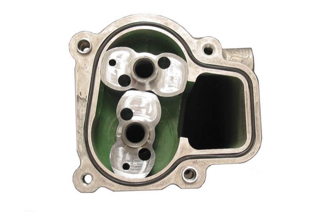
They are timed and driven by a pair of gears that are mounted on the same shafts as the lobes, which can be a disadvantage as extra room is needed to house the timing gears. As the lobes come out of mesh they create an expanding volume in the inlet port.
The movement of oil in an external lobe pump follows the same principle as in an external gear pump. The lobes rotate to create an expanding cavity that is filled with oil. The oil rotates around in the lobes until the lobes mesh again, forcing the oil into the outlet port and out of the pump.
External lobe pumps are sometimes referred to as a Roots pump, named after the American inventors and brothers Philander and Francis Marion Roots, who established the Roots Blower company in the 19th century. The lobe concept used in a Roots-type air induction blower is similar to that used by external lobe oil pumps.
External lobe pumps make an excellent choice for scavenging oil out of the engine because they are capable of pumping much larger volumes than could be attained with an external gear pump. This extra pumping capacity means they will also remove the crankcase gases, which creates a beneficial depression in pressure within the crankcase. In addition, because the lobes don’t contact one another, they don’t suffer from wear damage when pumping just air.
Early rotor lobe profiles were generated from a series of radii, but now more complex curves can be constructed to optimise the amount of volume displaced by the meshing lobes. The profiles of the lobes tend to be a mixture of epitrochoid and hypotrochoid curves used in internal gear pumps.
The number of lobes is another source for development. Traditionally, scavenge pumps would have twin lobe rotors, but there has been a trend to increase the number of lobes to three or more per rotor. While two-lobe rotors will have lower frictional losses than multiple-lobe rotors, having more lobes can help the rotor withstand the ingestion of debris.
As already discussed, the disadvantage with any positive-displacement pump is that the teeth come in and out of mesh, resulting in a variation in output pressure. On a lobe pump, one way to alleviate that is by using helical lobes that are twisted rather than straight. Although such helical gears can promote axial forces on the rotor, they have been proven to give a smoother flow of oil at steady speed.
Lobe pumps can be very efficient as they can offer a much larger ratio of displaced volume per unit volume than their geared counterparts (in effect, the volume between the lobes is larger than the volume between the gear teeth). However, there is a chance of more leakage in a lobe pump as the route back between the rotors is less convoluted than that in an internal gear pump.
This is particularly true with a twin-lobed rotor, so the clearance from the tip of one lobe to the base circle of the other needs to be as small as possible. That can only be achieved with precision machining of the rotor profiles and extremely accurate positioning of the rotor bore and journal bores in the housing and cover.
Pump Efficiency
There are a couple of useful parameters to describe how the efficiency of an oil pump: volumetric efficiency and overall efficiency, which are both expressed as a percentage. Both have to be obtained from empirical tests that are normally carried out on a test rig. Typical values of volumetric efficiency and overall efficiency vary markedly depending on the type of pump, and will also change with speed and pressure.
Volumetric efficiency is defined as the ratio of the actual volumetric amount of fluid moved by the pump compared with theoretical volume of fluid that should be moved. The actual volumetric flow rate has to be measured with a flow meter, and it is important to include the flow through the pressure relief valve if one is present.
Complex equations and CFD (computational fluid dynamic) simulations can be derived to determine the theoretical flow rate, but there is a simpler approach that will give a good approximation. First, measure the volume of the gear tooth space; normally this can be determined from a CAD model. The theoretical volumetric flow rate is then the product of the tooth space volume, the number of teeth and the rotational speed of the gear.
The overall efficiency is the ratio of the hydraulic power created by the pump relative to the (input) power required to drive the pump. The input power has to be measured, normally by fitting a torque sensor to the pump drive, and the input power is then the product of the measured torque and the rotational speed of the pump drive. The hydraulic power is then the product of the measured flow rate and the pressure rise delivered by the pump.
The goal for most race engine oil pump designers is to minimise any losses in the amount of hydraulic power generated by the pump. Some of these are attributed to the journal shafts running in the housing, cover and seals.
Further, in a gerotor pump, most of the mechanical losses come from viscous drag on the outer diameter of the outer gear and its end faces, hence such pumps will sometimes incorporate low-friction coatings in the bore and faces of the housing and cover. In a gerotor pump, reducing the outer diameter of the outer gear can be very beneficial to reducing viscous drag.
The clearances between the inner and outer rotors and the housing will also have a large effect on both volumetric and overall efficiency, so the lengths and diameters of the rotors and housing bore have to be tightly controlled. For example, most gerotors for oil pressure pumps will have clearances of around 0.1 mm radially between the outer rotor and the housing, 0.05 mm axially between the rotors and the housing, and tip clearances of around 0.08 mm.
These clearances are compounded by tolerance stack-up of multiple parts. For example, to achieve the axial clearance of 0.05 mm the tolerance on the length of rotors and the depth of the housing bore have to be around 0.025 mm per part. Minimal clearance will mean less loss due to leakage of the oil across the end faces from the pressure side to the suction side, but too little clearance can cause binding of the rotor. It is also possible to have debris trapped between these end faces if there is insufficient clearance.
Pressure Control
Undesirable thrust loads on the rotor end faces can arise if there are excessive fluid pressures inside the pump, resulting in sometimes catastrophic seizure of rotors. Most pump manufacturers have their own design methods to avoid this build-up of back-pressure, with small ports and galleries helping to drain the oil from the faces.
Some oil pump designs include small, shallow pockets in the end faces of the housing near to where the gears mesh. These are intended to relieve the lateral forces created between meshing gears, and which would otherwise cause the rotor and journals to start to bind and seize in their housing bores.
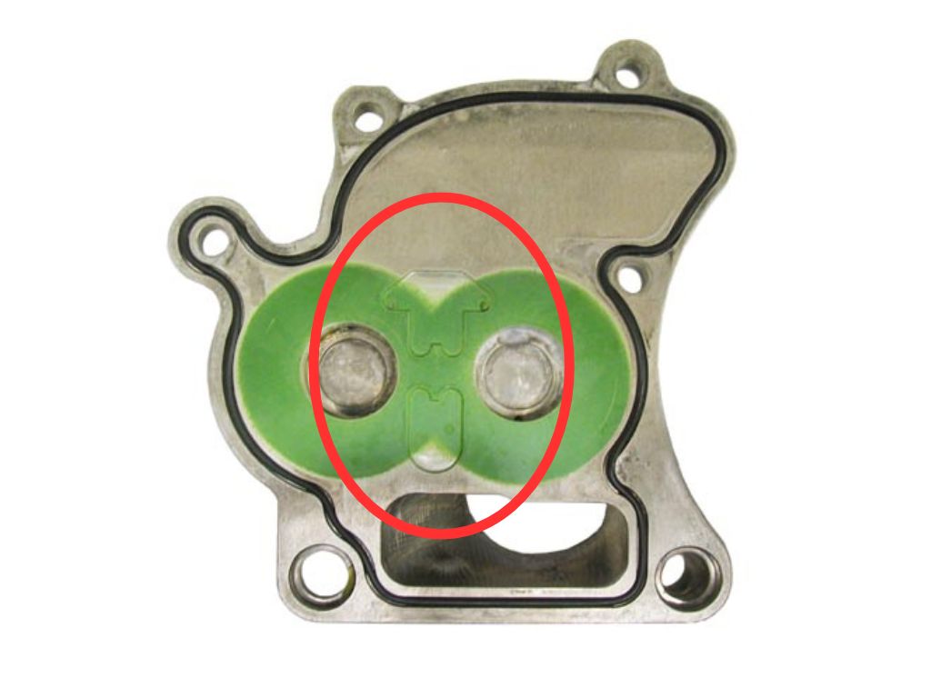
Also, most oil pressure pumps will incorporate a pressure relief or regulation valve to prevent over-pressurisation (you can read our technical blog on pressure relief valves here). As the output pressure is proportional to the pump speed, the valves are designed to operate at a pre-selected engine speed.
Most pressure relief valves consist of a spring-loaded piston. The spring rate and length are chosen so that the piston moves when the oil pressure reaches a desired value, and the piston will then slide to open a gallery to divert oil away from the high-pressure outlet, thereby capping the rise in pressure.
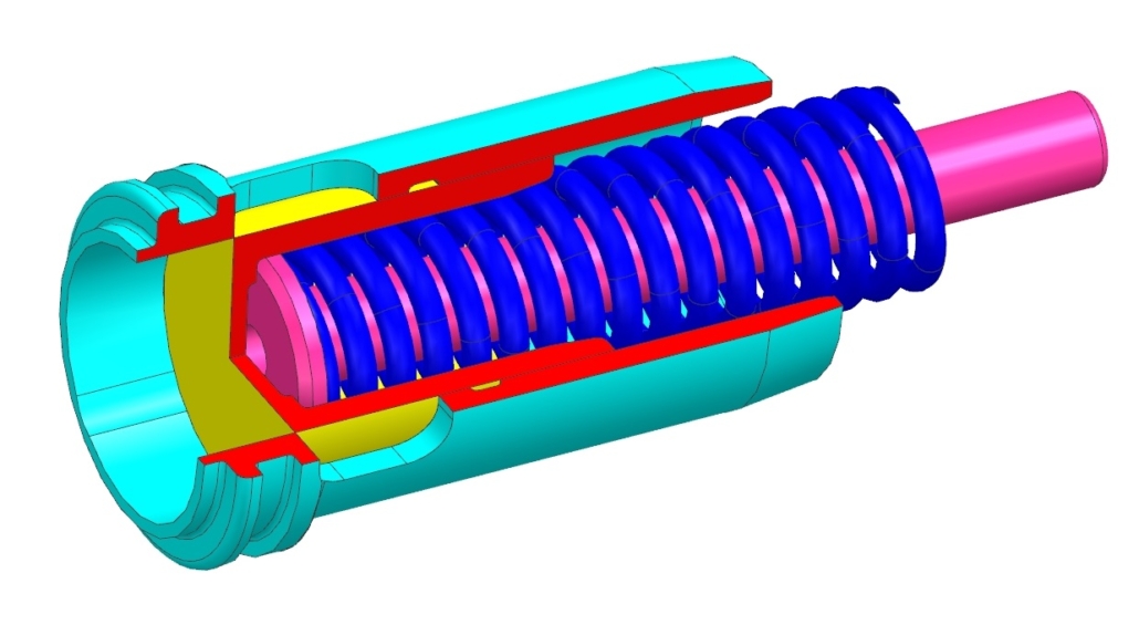
When designing pressure relief valves, consideration has to be given to where the by-passed oil will return to. Some designs will return the oil back to the pump inlet, whereas others will recirculate the oil back into the engine. Feeding oil back into the inlet can increase the oil temperature inside the pump and can also aerate the oil, which are both undesirable side effects.
Material Selection
As with any critical engine component in a race engine, the choice of material for the individual components in an oil pump needs careful consideration. While they may not be subject to the loads and stresses seen in other engine parts, oil pump housings still have to be able to withstand the stresses and deflections induced by the rotating internal components. And although a cracked oil pump housing or cover might not be catastrophic to start with, the consequences are still serious, as a gradual leakage of oil or reduction in oil pressure can eventually lead to engine failure.
Oil pump housings and covers are therefore normally made from a very high-grade aluminium alloy, with careful design to ensure that the rotor and journal bores remain as rigid as possible under all operating conditions. Aluminium is also an excellent material to machine, which can make it easier to achieve the very tight machining tolerances required. Some pump housings and covers are also anodised for protection against the harsh environments they find themselves in.
The rotors for both an internal and an external gear pump will be subject to very high contract stresses when the gear teeth mesh. Consequently, quite often they are made from high-grade steels, similar to gears from other drive systems in the engine.
There is however a fundamental problem when running steel rotors in an aluminium housing, and that is the different thermal expansion rates of the two materials. Aluminium has a thermal expansion coefficient that is more than twice that of steel, meaning that as the oil pump temperature increases, the housing will grow more than the rotors, which will lead to increased clearances, increased leakage and consequently a reduction in efficiency.
Some pumps will feature bronze or brass as the rotor material, as these materials are closer to aluminium in thermal expansion rates. Conversely, some pumps with steel rotors will have cast iron housings that have similar thermal expansion coefficients.
The rotors in an external lobe pump can enjoy a slightly easier life then their geared counterparts because the lobes don’t come into contact with one another, so there is no contact loading to worry about. This means that wear isn’t an issue on the lobes, and the materials used can be as light as possible, for example aluminium alloy or even carbon fibre. However, caution has to be applied to the wear properties of the lobes as they will have to cope with any debris sucked in from the crankcase, hence the need for good filtration on the scavenge pump inlet.
Coatings are another option that manufacturers can turn to, either to combat wear between the meshing gear teeth or to reduce friction between running surfaces, particularly between the end faces of the rotors and the flat faces of the housing and cover. PVD-applied coatings such as DLC can help to reduce wear, and PTFE-type coatings have been used over the years to reduce friction.
This feature on crank bearing lubrication is based on an article written by Modatek’s Matt Grant for Race Engine Technology, issue 105. You can purchase a back copy of this publication here: https://www.highpowermedia.com/Product/race-engine-technology-issue-105


