OIL PUMP PRV TECH
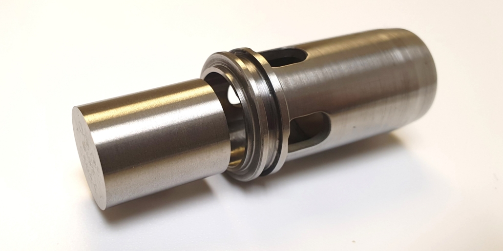
Every engine lubrication system needs pressure to move the oil around the myriad of galleries and drillings inside the engine. One or more pumps will provide the pressure, and the most common way to regulate the pressure is with an oil pump PRV (pressure relief valve) like the one shown below.
The oil pump is a pulsating heart that continually moves the oil so that it can lubricate running surfaces and remove heat from critical areas. If a typical high performance engine has an oil flow rate of around 60 litres per minute and an oil volume of around 6 litres, that means that in the 30 seconds or so that it’s taken you to read this far, the oil in the lubrication system will have already been pumped around the engine five times.
All engines need at least one oil pressure pump to create enough pressure to push the oil around the oil circuit. In addition, an engine with a dry sump will also have one or more scavenge pumps, whose job is to remove the oil from the various sections of the engine.
Positive-Displacement Pumps
Both oil pressure pumps and scavenge pumps tend to be of the positive-displacement type, whereby the internal elements of the pump move to create a void that opens up and expands, filling the void with oil. The elements continue to move in a manner that then compresses the void, forcing the oil out of the pump and into the oil circuit.
A high performance oil pump normally contains rotating elements such as rotors or gears, and they typically either run inside one another (classed as an internal gear pump) or side by side (referred to as an external gear pump).
These rotating positive-displacement pumps need a rotary drive, which on most race engines comes courtesy of the crankshaft or camshaft, either directly or from gears, chains or belts that in turn are connected to the crankshaft or camshaft. Consequently, the pressure delivered by the pump increases with engine speed.
In the most extreme circumstances, if the pressure in the oil circuit isn’t regulated then it could rise to such a level that could damage the engine. For instance, extreme pressures could rupture the oil filter or blow out any sealing plugs. Most oil circuits will therefore include at least one device that can control and regulate the pressure, to make sure it can’t exceed a predetermined maximum level.
Spring-loaded Piston PRV
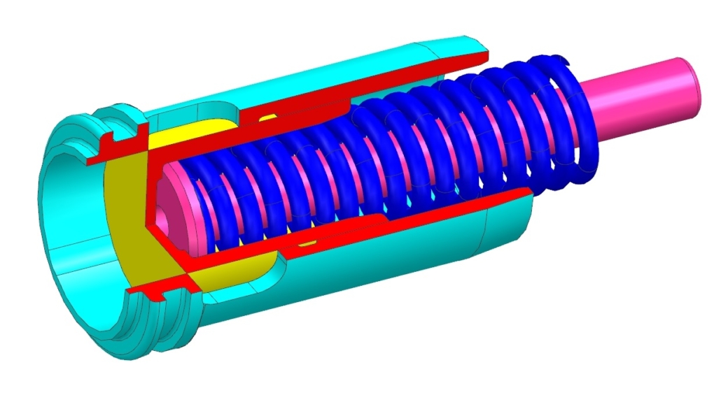
The majority of PRVs are constructed from a spring-loaded piston, which moves when the oil pressure in the dead space above the piston reaches a certain level. When the piston moves, it reveals a port that allows the oil to vent out of the pump, thereby capping the oil pressure. While the theory behind such a device is relatively simple, as ever the devil is in the detail.
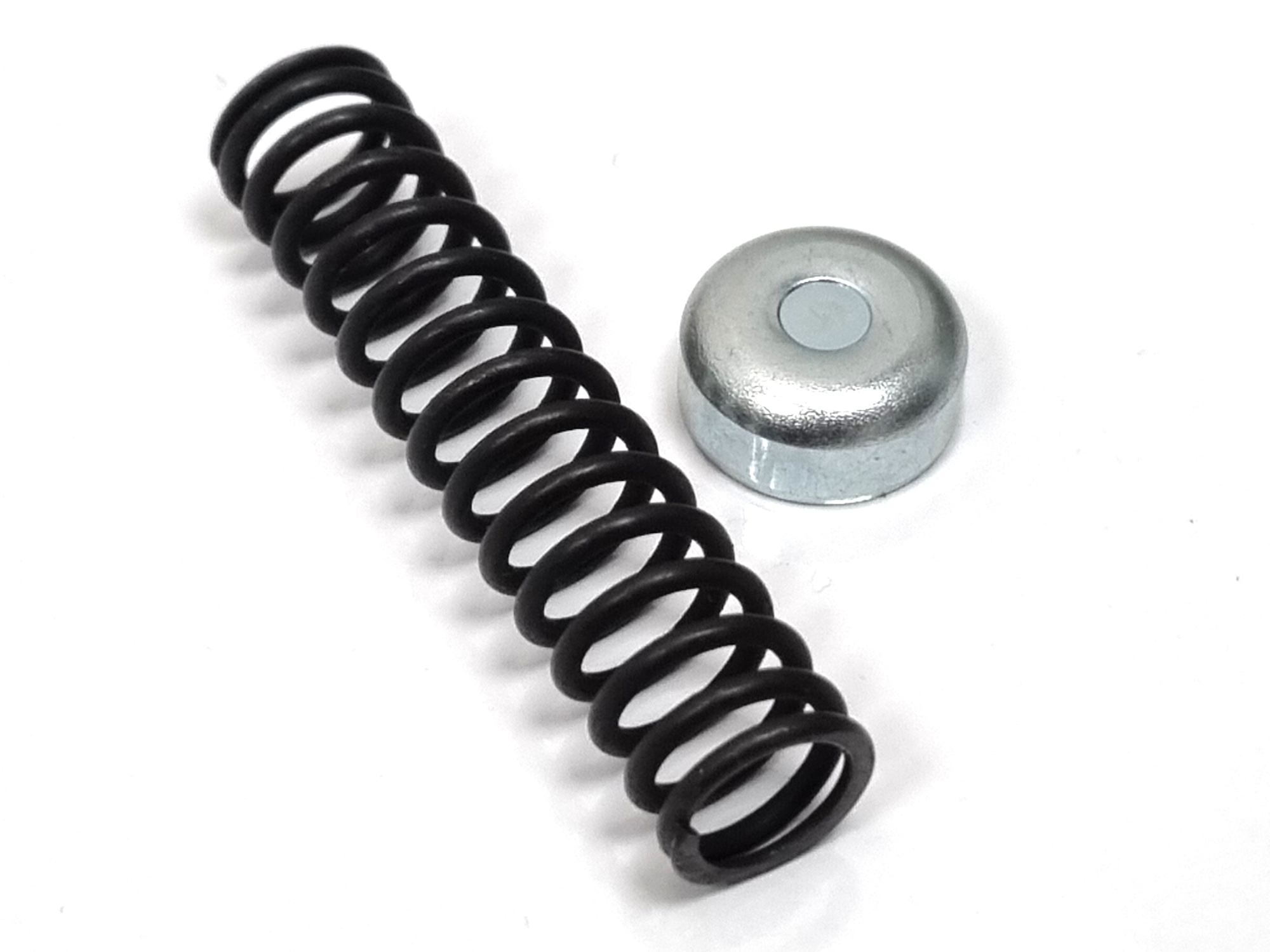
The operation of the oil pump PRV depends on a correctly defined spring (the one pictured above is our high pressure spring for the Cosworth YB oil pump). Some good old-fashioned engineering equations can give accurate results to define the spring required in the PRV.
Let’s use the following terms:
- Required PRV opening pressure = Preq
- Spring force = F
- Piston radius = r
- Spring rate = k
- Length of travel of piston required to open PRV outlet port = x
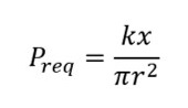
The pressure on the piston is simply the spring force divided by the piston area, which is:
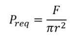
The spring force can be derived from Hooke’s Law:
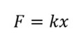
Combining these two equations, we get:
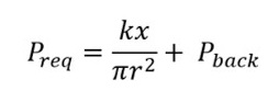
However, we must also consider the back-pressure on the other side of the piston, downstream of the PRV. Although small, the back-pressure will affect the movement of the piston and should ideally be less than 10% of the required opening pressure of the PRV.
This back-pressure is a result of a huge range of variables, such as bearing clearances, oil viscosity and temperature, flow passage size and roughness, plus more. It is therefore hard to calculate but can be found from measurements taken when the engine is running.
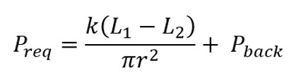
The back-pressure will have an effect on the required pressure, and hence needs to be included in the calculation. If we term the back-pressure as Pback, then the calculation for the required pressure becomes:
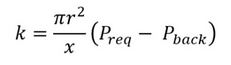
So, if we’ve already decided on the piston radius and the length of travel of the piston (which is normally dictated by the space that is available for the PRV), we can rearrange this equation to choose the correct spring rate that will correspond with the required opening pressure:
Armed with this information, the spring designer can decide on the wire diameter, coil diameter, number of active coils and shear modulus to give the required spring rate, k, from this equation:
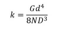
where d is the wire diameter, D is the coil mean diameter, N is the number of active coils and G is the shear modulus.
Spring Stress
The spring designer also has to check that the torsional stresses in the spring are within safe levels, so that the spring doesn’t elastically deform or break. FEA is one way to determine the stresses, but again some simple calculations can also be used to good effect.
The torsional stress τ in a spring under load F can be found from the equation:
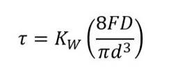
KW is known as the Wahl factor, and is a corrective factor that takes into account the effect of direct shear and the change in coil curvature, and can be found from this equation:
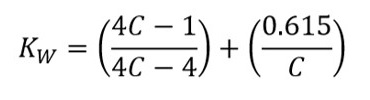
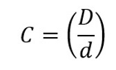
where C is the spring index:
Checking the stresses in a PRV spring might seem unnecessary, but the effects of a broken PRV spring can be as serious as a failed valve spring. The PRV will continue to operate with a broken spring, but if it opens at a lower pressure than required, the oil supplied to critical components such as the crankshaft bearings and piston squirt jets will be at a lower pressure, and like a broken valve spring, the result can be catastrophic engine failure. Combining the above series of equations into a spreadsheet though can enable a PRV designer to quickly establish the link between required pressure and torsional stress in the spring.
Adjusting the Required Pressure
It is also possible to modify the required pressure of an existing PRV without resorting to changing the spring. If the spring has a fitted length of L1 and the length of the spring is L2 when it is compressed by x, then:
We can see from this equation that we can increase the required pressure by reducing the length of spring when it is compressed (L2). In reality, this can be done during assembly of the PRV by adding one or more shims to one end of the spring.
Oil Pump PRV Reliability
One would think that being constantly flushed with oil, the piston would be free to move up and down the cylindrical bore in the sleeve without any issues. However, one of the biggest problems with spring-loaded piston PRVs is that they can tend to jam. That is especially true if dirt or debris gets trapped in the gap between the piston and the bore.
For this reason, suitable filtration of the oil is vital, and usually the oil pump PRV is located downstream of the oil filter so that it receives the oil in its cleanest state.
Also, the clearance between the piston and the cylinder is kept as low as possible, to keep any contaminants out. It’s not uncommon for the piston and the sleeve to be machined as a matched pair. Normally the piston diameter will be measured, then the bore in the sleeve will be machined to the correct size to give the required clearance for that particular piston.
Some PRVs have clearances as low as 5 microns, so it’s essential that this machining is as accurate as possible. Usually, the piston is ground and the bore in the sleeve is honed, as both of these manufacturing methods result in an extremely low dimensional tolerance of just a few microns and can give exceptional levels of circularity and run-out.
The material for the piston and sleeve tends to be as hard as possible, so that any debris doesn’t scratch the walls of both parts. Also, the leading edge of the piston is normally kept as sharp as possible – even a small chamfer can trap debris that will then find its way into the radial gap between the piston and bore.
Also, it is important that the piston and sleeve are demagnetised, otherwise small magnetic forces can cause the piston to stick.
Oil Pump PRV Bypass Return
The choice of where to route the oil that comes out of the PRV bypass seems to be a matter for debate. The two options are to feed the oil back to the oil pump’s inlet or to ‘dump’ the oil back into the engine, usually into the sump or oil tank. Returning the oil from the PRV to the oil pump inlet is the more popular option on race engines.
One benefit of returning the PRV flow back to the oil pump inlet is that it can help to prevent the onset of cavitation. Briefly, cavitation is the damage caused to a surface by the formation of tiny bubbles in the oil. The bubbles are created when the pressure in the oil drops below the oil’s vapour pressure. The oil will boil, instantaneously creating thousands of these tiny bubbles. When the pressure in the oil rises above the vapour pressure again, the bubbles instantly collapse.
This rapid movement of oil leads to small zones of highly pressurised oil, which when combined with the shockwaves from the collapsing bubbles can result in pitting of any nearby metallic surfaces.
There are a number of tricks that can stop cavitation, and most methods are aimed at increasing the pressure at the inlet to the oil pump. For example, if there is a filter on the pump inlet then the mesh size could be increased, or the inlet port to the oil pump could be contoured to help the oil flow more easily into the pump.
Oil Pressure Requirement
I have designed numerous oil pump PRVs in my time, and I’ve found that the most difficult part of the process is actually deciding the pressure the PRV should open up at. Ask a group of engine designers how much oil pressure an engine needs and you’ll probably receive a number of conflicting answers.
Some will say the pressure needs to be high enough to keep highly loaded bearings lubricated or to feed the piston squirt jets. However, others will say the demands of creating too much pressure can increase the parasitic power losses, so it needs to be as low as possible.
In truth, the exact oil pressure required will normally be decided only after multiple tests, either in the car or on a dynamometer. It is important therefore to make sure the designed PRV has room for adjustment, as mentioned already by the use of shims or via an external adjustment device.
An old rule of thumb used to be that an engine needs 10 psi of pressure for every 1000 rpm of engine speed, so for example an engine that revs to 8000 rpm will need 80 psi. In reality, that is probably an over-cautious estimate for modern race engines. Developments in both lubrication and bearing technology mean that the higher grades of oils used in a race engine can withstand more extreme pressures in the plain bearings of the crankshaft (the area in which the oil is typically the most stressed), and enhanced additives allow the oil to behave better for longer.
One train of thought is that the required oil pressure is closely related to the clearance of the crankshaft bearings combined with the viscosity of the oil, because oil pressure can drop if the viscosity is reduced or if the bearing clearance is opened up. Given that reduced bearing clearances can have a positive effect on power, some engine builders will offset the increase in required pressure that might arise from reducing bearing clearance by running lower viscosity oils.
In truth, one has to consider the various sources of pressure drop along the entire lubrication circuit when specifying the oil pump’s required pressure. Some pump designers will group these sources together to come up with an ‘effective orifice area’, which is the equivalent flow area of all of the holes and gaps that the oil has to flow through. It will be a combination of the bearing clearances, plus clearances to other mating parts such as camshaft followers along with small holes such as those in squirt jets.
Broadly speaking, oil pressure is proportional to both the effective orifice area and the oil viscosity: the oil pressure rises if either the effective orifice area or the oil viscosity is increased. This can be observed when starting a cold engine – the lower temperature means the clearances are small and the oil is thicker. Both of these effects combine to give higher oil pressure.
As the engine gets hotter, the clearances in the engine begin to open up, and the oil gets thinner. The increase in both the effective orifice area and the oil viscosity will result in a drop in oil pressure, so it is vital to make sure that the chosen oil pressure requirement is optimised for the required range of temperatures the engine will experience.
This feature on oil pump PRVs is based on an article written by Modatek’s Matt Grant for Race Engine Technology, issue 136. You can purchase a back copy of this publication here: https://www.highpowermedia.com/Product/race-engine-technology-issue-136

