CRANK BALANCING TECH
An essential stage when designing a crankshaft is to ensure that it is as well-balanced as possible. This is normally done with the addition of counterweights, which will counteract the inertia forces and couples created by the rotating and reciprocating masses. If a crankshaft is not correctly balanced then it can lead to excessive vibration, which will have a detrimental effect on reliability.
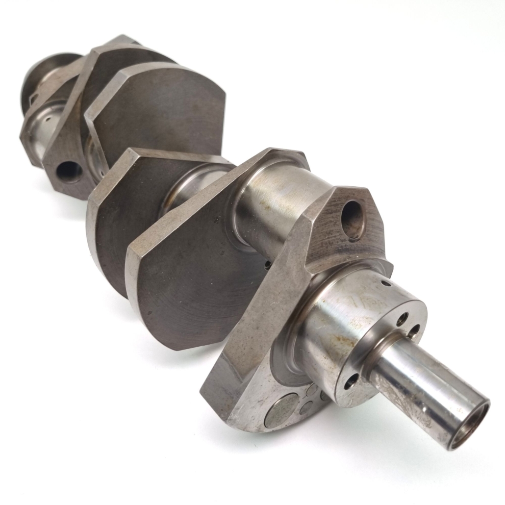
At the heart of every piston-powered engine sits a crankshaft, to convert the reciprocating motion of the pistons into rotational movement. The movement of these piston assemblies, connecting rod assemblies and the crankshaft itself creates large inertia forces and couples, which in most engine configurations have to be balanced out with webs and counterweights on the crankshaft. These forces and couples will manifest themselves as vibration, which if ignored can drastically reduce the reliability of both the engine and the car.
Bad Vibrations
A poorly balanced crankshaft can drastically reduce the reliability and performance of an engine. First of all, the out of balance forces will subject the main journal bearings to higher loads than they are designed for. Most main journal bearings are plain bearings, relying on a constant film of oil for lubrication; an increase in load will reduce the oil film present, which in turn will lead to a loss of power. Should the oil film start to break down under excessive loading, then the bearings will wear out quicker than intended.
The imbalance within the crankshaft may cause it to distort (both in bending and in torsion). This distortion also has a negative effect on main journal bearing performance as the edge loading of the bearing is increased.
Externally, the loads from the crankshaft are transmitted to the mating chassis through the engine mounts. It is often not possible to incorporate any damping into these mounts, particularly when an engine is installed onto the back of a single-seater monocoque, so these vibrating loads are passed through to the driver; in the past, drivers have been known to suffer from visibility issues when racing because of badly balanced crankshafts.
Vibration from the engine will also affect the reliability of components mounted to the chassis, from minor ancillary parts through to important structural members. So a car’s reliability can sometimes be greatly improved just by better crank balancing.
Calculation of Balancing Forces
While the primary objective of the crankshaft is to convert the reciprocating motion of the pistons into a rotation movement that will turn the engine’s output shaft, it also has another job to do: to provide opposing forces and couples to balance the forces from the moving parts in the crankcase, thereby reducing the amount of engine vibration.
A perfectly balanced engine would exhibit no vibration, such that it could be suspended in mid-air and not move. Of course, in reality that is almost impossible; however, the dynamic forces and couples can be virtually eliminated for some engine configurations.
As mentioned, the dynamic forces are due to the movement of the internal masses within the crankcase. The masses attached to the crankpins can be broken down into two categories: rotating and reciprocating.
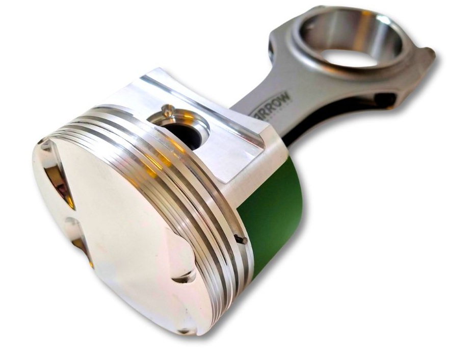
Rotating masses consist of the crankpin bearings, big-end bolts and a proportion of the connecting rod mass that is centred on the crankpin. Also not to be forgotten when considering the rotating mass is that of the crankpin itself, plus any lightening hole bungs that might be present. The reciprocating masses will include those of the piston, gudgeon pin, bush, rings and clips, plus the rest of the connecting rod.
The proportions of rotating and reciprocating masses of the connecting rod are normally expressed as the rod’s big-end and small-end masses, and are derived by taking moments about the rod’s centre of gravity. Assuming that a 3D CAD model of the connecting rod exists then most CAD software packages can quickly give the position of the centre of gravity for the rod. Alternatively, before the advent of CAD, the traditional method to determine the big- and small-end masses would have been to weigh the connecting rod on two scales, with one scale on the split line between the rod and cap and the other on the small-end centreline, whilst keeping the connecting rod centreline horizontal.
Next, consider the reciprocating motion of the piston. The acceleration of the piston can be broken down into a series of sinusoidal waves, which can be expressed as:
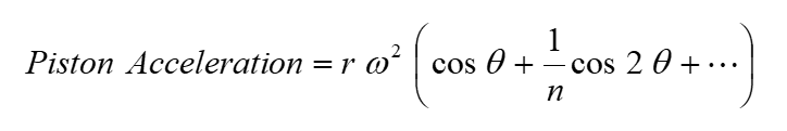
where θ is the crank angle from the cylinder centreline, r is the crank throw, n is the crank throw divided by the rod length and ω is the angular velocity of the crankshaft. There are higher-order cosine terms, but these are not normally considered.
It follows that the inertial force Frec created by the reciprocating motion of the piston is:
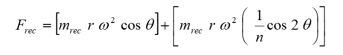
where mrec is the mass of the reciprocating parts. The first half of this equation is termed as the primary reciprocating force, and the second half the secondary reciprocating force. As these primary and secondary forces act along the cylinder centreline, they will create a corresponding primary couple and secondary couple about the front and rear main journals.
There is also an inertial force Frot and associated couple created by the rotating components, which can be found from the equation:
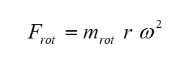
where mrot is the mass of the rotating parts.
In a similar manner, the inertial forces Fweb from the rotating webs (including counterweights) can also be found, as:
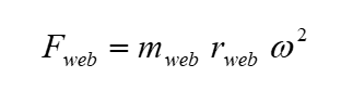
where mweb is the mass of the web (including counterweight) and rweb is the distance from the centre of gravity to the crankshaft centreline. A 3D CAD model can give a very good measure of both the mass and the position of the centre of gravity of each web.
The inertial forces and couples from the webs will only be able to balance out the forces that are occurring at once times engine speed. The secondary forces are occurring at twice engine speed, and so would need to be balanced out by external balance shafts rotating at twice engine speed.
As it is not possible to completely balance out the secondary forces and couples, crankshaft designers often cite a balance factor, usually as a percentage. That is the percentage of the reciprocating mass that when added to 100% of the rotating mass will be balanced by the webs (including counterweights).
Typical values for balance factors are around 50% for most crankshafts; anything lower will give a lighter crankshaft but at the detriment of balance. Ultimately, the chosen balance factor is a compromise between crankshaft weight, main journal bearing performance and engine vibration.
Aside from the design of the crankshaft webs, the other crucial factor in engine balancing is the configuration of the cylinders in the engine. The number of cylinders, and for vee arrangements the angle between the two banks of cylinders, will have an enormous effect on the summation of the inertia forces and couples. In some layouts, particularly those where two banks of cylinders are opposing one another (usually termed a ‘boxer’ layout), the first- and second-order forces can cancel one another out.
The Bosch Automotive Handbook gives a very concise summary of the first- and second-order forces and couples for a number of popular cylinder arrangements. The configurations that will have zero first- and second-order forces include the inline three-cylinder, four-cylinder opposed, inline five-cylinder, six-cylinder 90° vee, six-cylinder 60° vee and eight-cylinder 90° vee layouts. Even better are those arrangements that also have zero second-order forces and couples, which include inline six-cylinder, six-cylinder opposed, and 12-cylinder 60° vee layouts.
Its worth mentioning that crankshafts are normally also dynamically balanced after manufacture. The out-of-balance forces and couples can be measured by spinning the crankshaft on a balancing machine, and material can be removed from highlighted areas on the crankshaft to bring these forces and couples down to below preset targets.
Introducing the Modatek Crank Calculator
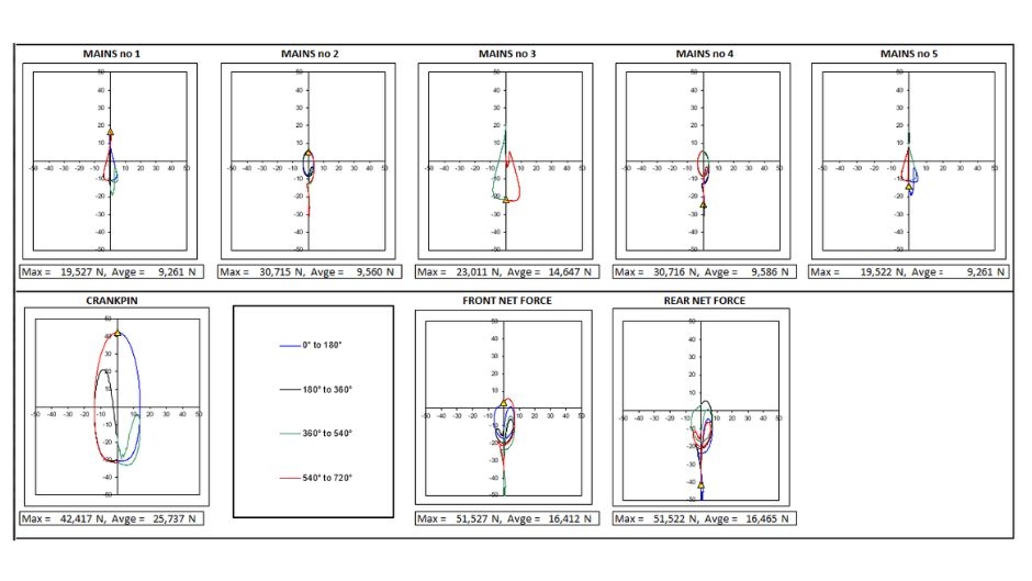
There are many different methods used by crankshaft designers to ascertain the required balancing and then decide on the shape of the webs. Using the theory shown above, it is possible to construct a spreadsheet in Microsoft Excel to calculate the reciprocating and rotating inertial forces acting on the crankshaft at a given crank angle and engine speed for each cylinder and web along the length of the crankshaft. Taking moments about the main journal centre positions, the spreadsheet can then be used to determine the inertial forces and couples that are transmitted to the main journals.
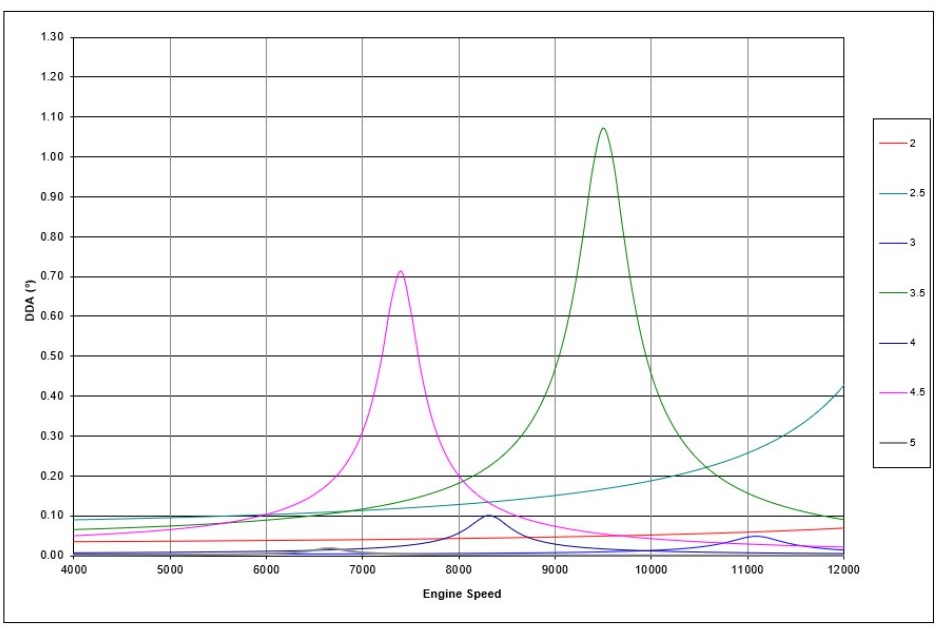
At Modatek, we’ve gone one step further (well, quite a few steps actually). We’ve combined the crank balance calculations with our own crankshaft torsional calculator, to create a tool that can predict rod and main bearing loads, front and rear net forces, torsional frequency and torsional ampltitude.
We’ve been gradually developing this tool, and its now available for a number of different engine configurations, including inline-4 and V6 layouts.
If you’d like to learn more about our crankshaft calculator then get in touch!
This feature on crankshaft balancing is based on an article written by Modatek’s Matt Grant for Race Engine Technology, issue 99, and back copies of this publication are still available.

Leave a Reply
Want to join the discussion?Feel free to contribute!