THE BIRTH OF AN ICON – THE COSWORTH DFV
It’s now 57 years since the introduction of what would become the most successful Formula 1 engine in history. The Cosworth DFV engine won on its debut at the Dutch Grand Prix in 1967 and would go on to dominate in Formula 1, racking up 155 victories. No other engine has come close. Using notes that were prepared by company founder Keith Duckworth and chief designer Mike Hall, along with feedback from one of Cosworth’s long serving employees Malcolm Tyrrell, we take a look at the birth and technical spec of the early iterations of this incredible power plant.
Cosworth had already become an established name in the motor racing world with its successful Formula Junior, Formula Three MAE, Racing Lotus Twin Cam and Formula Two SCA engines, based on standard cylinder blocks with bespoke cylinder heads. But then, at the end of 1965, Cosworth embarked on a completely new project that would establish its name in racing for ever. In exchange for £100,000 from the Ford Motor Company, Cosworth would create a four-cylinder Formula Two engine, the FVA (Four Valve Type A), which would then be ‘doubled up’ to create a V8 for Formula One, the DFV (Double Four Valve).
For nine months in 1966, Duckworth entrenched himself in a room at his house, working every day from 9am until past midnight. Once a week he would visit the factory to hand over schemes and drawings, and get feedback on the progress of the manufacture of his designs. Chief designer Mike Hall joined Cosworth from BRM in October 1966, and was instrumental in the detail design of the major components and all auxiliaries, working from Duckworth’s layouts. The engine was completed in April 1967, winning first time out at the Dutch GP in June in Lotus’ new Type 49 chassis.
As per the contract with Ford, Duckworth and his team started with the FVA, incorporating the lessons learnt on this four-cylinder engine into the design of the DFV. Duckworth set a power output target for the FVA of 200 hp, reasoning that the DFV would need 400 hp to be a winning engine. As it turned out, both these performance targets were comfortably exceeded.
Engine Mounting and Layout
The oval shape of the Lotus 49 monocoque meant it would be difficult to extend the sides of the chassis down past the engine, resulting in the dictate from Lotus’ Colin Chapman that the engine should be a stressed member of the chassis from the outset. Part of the suspension would also mount directly to the engine; schemes and handwritten notes still at Cosworth show that the layout of the suspension went back and forth between Duckworth and Chapman before settling on the final positions.
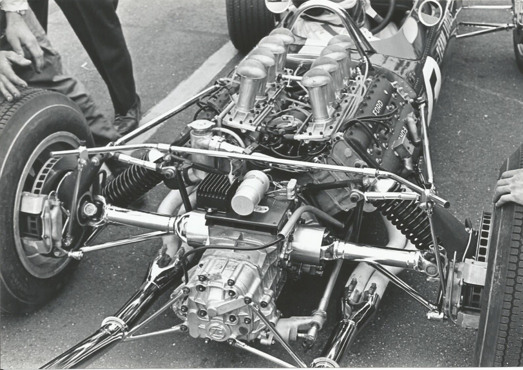
The engine was bolted to the bottom of the rear of the monocoque bulkhead by a wide-based bracket on the sump, with the intention that these lower mounts would transmit the shear loads between the chassis and engine. Anecdotally, Duckworth would remark that the distance between the two engine mounting bolts at the front of the engine was chosen to match the width of Jim Clark’s posterior! At the top of the engine, the left- and right-hand cam covers were connected to the top corners of the rear bulkhead with thin triangular shaped steel plates, so as to take the tension and compression loads. The plates were also intended to deflect under the thermal expansion of the engine, calculated at the time to be 0.015 in (0.4 mm).
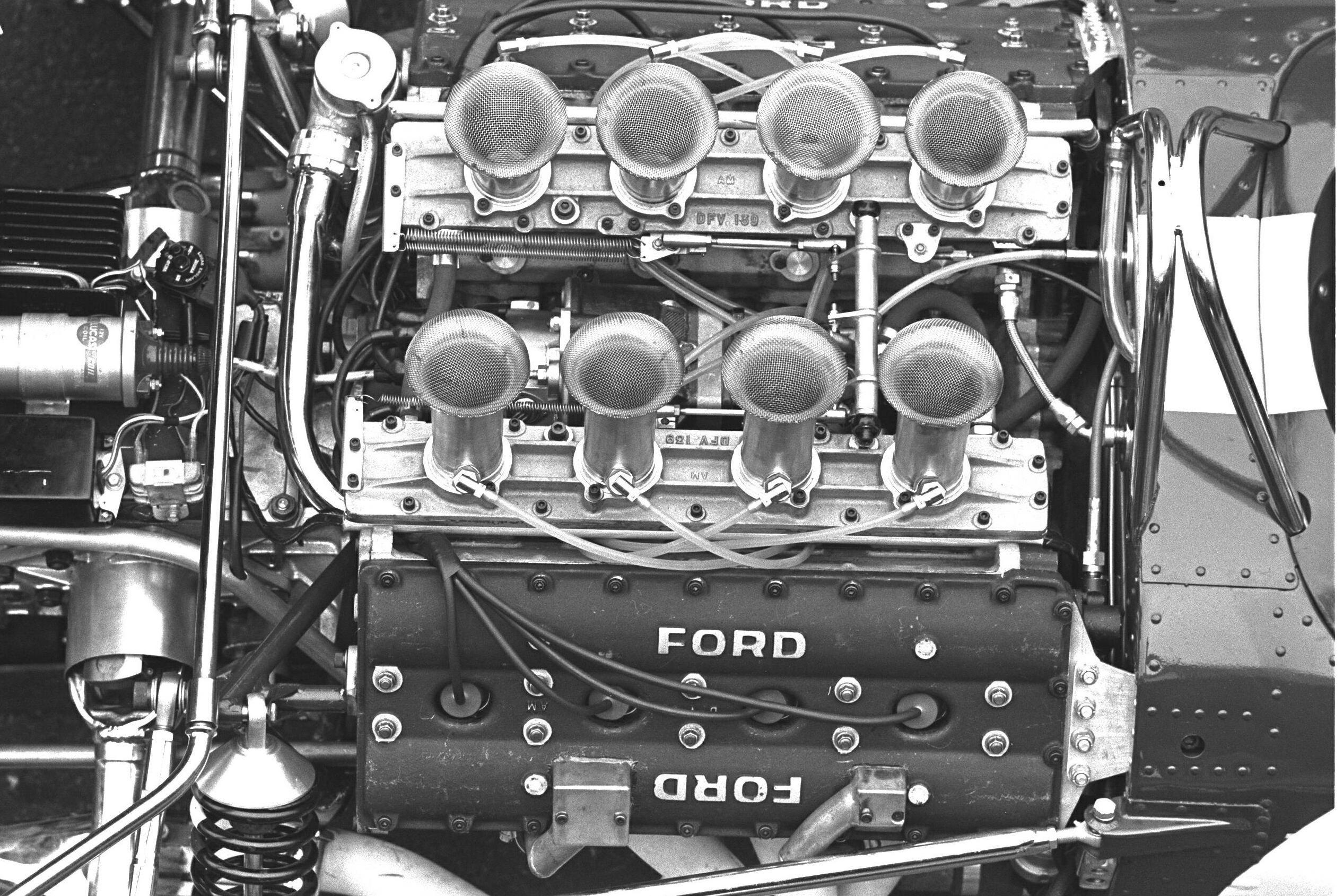
Duckworth was intent on keeping the engine as compact as possible, so to keep the front of engine flat and uncluttered he positioned the water, oil and fuel pumps along the sides of the cylinder block underneath the exhaust pipes. That would also allow for a lower centre of gravity, recorded at 4.6 in (116.4 mm) above the crank centreline. The left- and right-hand pump pulleys were driven at the front of the engine using a Uniroyal toothed rubber belt, driven from a pulley connected to the second compound gear running at half engine speed.
The overall dimensions of the Cosworth DFV engine showed that it was wider and higher than it was long – the height of the engine from the bottom of the sump to the top of the trumpets was 23.3 in (590 mm), the length measured at 21.6 in (550 mm) and the overall width between the extremities of the cam covers was 26.8 in (680 mm). With no clutch or starter motor fitted, the dry weight of the engine came out at 350 lb (159 kg).
Crankcase
With the rules stating that the DFV had to have a capacity of 3 litres, the individual cylinder capacity was reduced from 400 cc on the FVA to 375 cc on the DFV. The DFV copied the FVA’s bore diameter of 3.373 in (85.67 mm), with the smaller cylinder capacity achieved by a shorter stroke of 2.550 in (64.77 mm) to give a total capacity of 2993 cc.
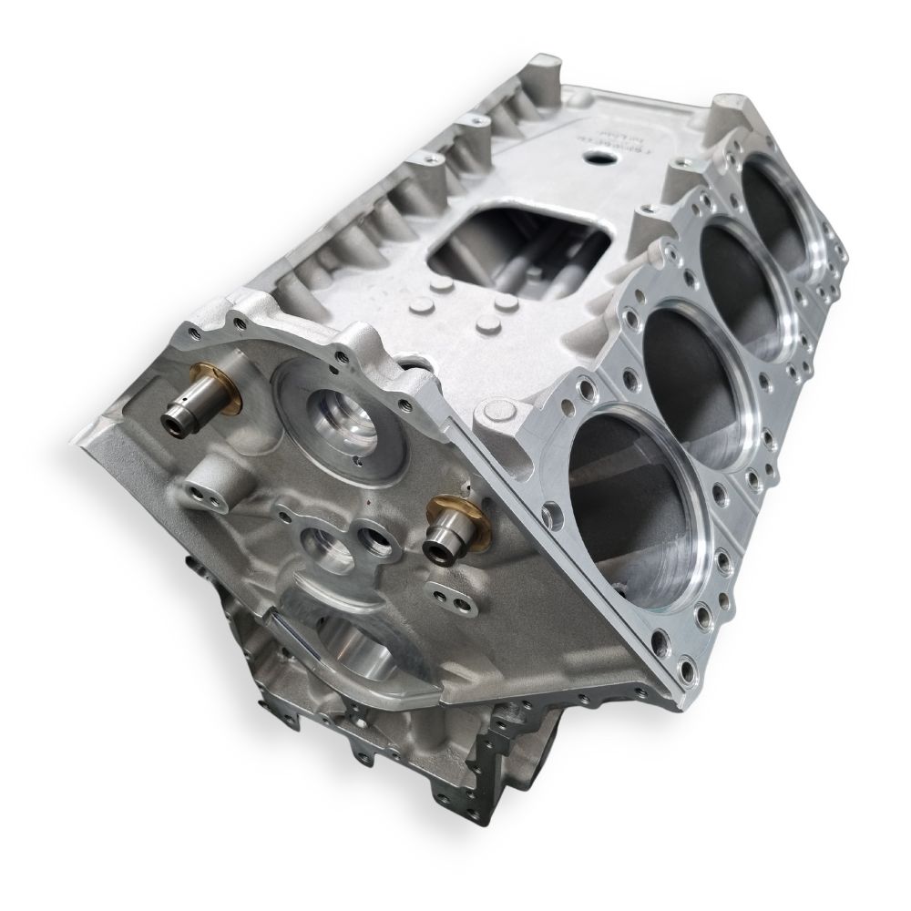
Like most of the other major castings, the cylinder block was created from fully heat-treated 7% silicon LM 25 aluminium. At the time, this material was considered to be the best commercially and readily available alloy in the UK, with the highest proof stress and Brinell hardness, and good casting and machining capabilities.
In the cylinder block were wet liners machined from centrifugally spun castings, made from chrome vanadium alloy iron. They were interfered into the block with two O-rings at the bottom of each liner to seal off the crank case chamber. The top of the flange on the liner had a recess for a Coopers sealing ring.
The sump was made up of box sections that ran from front to rear and across the engine to try to maximise stiffness. The box section at the front also carried water to connect and balance the two water pumps on either side, while the rear box section carried the scavenged oil to an outlet on the left-hand side of the engine.
Water Pumps
The first iteration of DFV engines had a single water pump, mounted on the right hand side, directly in front of the oil scavenge pump. Later DFV iterations featured two water pumps mounted on either side of the engine, so that each bank of the engine was cooled by its own water pump.
These later water pumps used 2.5 in (63.5 mm) diameter centrifugally bladed impellers contained within a volute spiral casing. Each pump had a maximum flow capacity of 45 gallons per minute (204 litres per minute), and the water flow from each pump was sufficient to restrict the temperature rise from the water pump inlet to the engine outlet to 7 C.
Fuel Pressure Pump
A mechanical fuel pressure pump was positioned at the front of the left-hand side auxiliaries. This gear-type pump was capable of delivering 40 gallons per hour (182 litres per hour) at maximum engine revs against a back pressure of 120 psi (8.3 bar). An electrically driven high-pressure pump was activated for starting purposes; this auxiliary pump was then switched off when the engine speed reached 2500 rpm.
The fuel pump was positioned as far out as possible so that it would be cooled by the air stream around the engine, in a bid to keep the fuel cold and prevent fuel vaporisation. A further measure to reduce fuel temperature included isolating the pump from its supporting bracket with a Tufnol insulator.
Oil Pressure Pump
At the rear of the left-hand auxiliaries sat the main oil pump incorporating an integral filter. The oil pump contained a 0.8 in (20.3 mm) wide Hobourn Eaton lobe-type rotor, which at maximum engine revs could displace 11 gallons per minute (50 litres per minute) against a 100 psi (6.9 bar) pressure relief valve setting.
A transfer pipe fed the filtered oil from the pump to the crankcase main oil gallery. From here the oil was fed to the five pairs of main bearings, and then through the cross-drillings in the crankshaft into the eight pairs of big-end bearings. It was estimated that at 11,000 rpm a minimum oil pressure of 68 psi (4.7 bar) was required to force the oil into the centre of the crankshaft due to the centrifugal head generated at this speed.
Oil Scavenge Pump
On the right-hand side of the engine were the scavenge pumps, two pairs of Hobourn Eaton form rotors with a separator between them, drawing oil in from the scavenge chambers in the sump. (Later pumps would feature Roots type rotors.)
Each cylinder head featured two head drains, one at the front and one at the rear, which fed down to the scavenge chambers. Finally, oil from the oil pump pressure relief valve was also fed directly into one of the scavenge chambers.
Early DFV engines suffered serious issues with bad draining of oil from the cylinder heads. The first engines only had a scavenge capacity of twice the oil pressure pump, so the scavenge pumps were unable to handle the oil and the blow-by gases. As a result, the blow-by gases would go up the head drains, preventing oil from coming down the other way, which caused the heads to fill with oil, eventually venting the oil to atmosphere and draining the oil tank.
Unable to increase the size of the head drains, a temporary sliding vane-type pump was fitted to take care of the blow-by. However, this in turned caused more problems, as the conventionally scavenged oil, which measured 11 gallons per minute (50 litres per minute), was now mixed with the equivalent of 40 gallons of air per minute (182 litres per minute). The resulting aerated oil led to the design of a centrifuge which ensured that the mixture returned to the oil tank contained 90% oil and only 10% air. This centrifuge was included in the new design of scavenge pump, which now had a capacity of 55 gallons per minute (250 litres per minute) – five times the capacity of the oil pressure pump.
Geartrain
Behind the front cover was a geartrain consisting of 14 gears. Assembled to the front of the crankshaft was the crank gear, which turned the first compound gear, an assembly of two gears. The smaller of these two gears drove another gear assembly, termed the second compound gear. This assembly was made up of three gears; a large central driven gear sandwiched between two smaller gears. To the left and right hand side of the second compound gear were the first of two head idler gears, driven from the outer gears of the second compound gear. On each bank, the first head idler gear turned the second head idler gear. Finally, the left and right hand second head idler gears drove the respective bank’s inlet and exhaust cam drive gear.
All the gears were made from forged vacuum re-melted EN39B steel blanks, case hardened to a depth of 0.020 in (0.5 mm). Considerable effort in production engineering and quality control was made to ensure that the teeth were accurately ground to ensure concentricity of their pitch circle diameters to the gear bearing bores, resulting in the required backlash and correct involute profiles.
However, despite the great attention to detail given to the design and manufacture of the geartrain, gear problems blighted the first race engines. At debut race of the Cosworth DFV engine, Graham Hill retired with cam gear failure, and broken gear teeth were found in the winning engine of Jim Clark. In addition, the gear failures were compounded by catastrophic valve spring failures when the engines were run at more than 9000 rpm. Cam lobes profiles were redesigned to bring down their maximum torque requirement from 36 lb-ft (49 Nm) to 26 lb-ft (35 Nm); however, even though the valve spring life improved, there were still gear failures.
Using strain gauges, instantaneous stab torques of 300 lb-ft (407 Nm) where recorded – far higher than the original torque calculations used for the gears. What was needed was a way to absorb the shock loading from the camshafts that was destroying the gears.
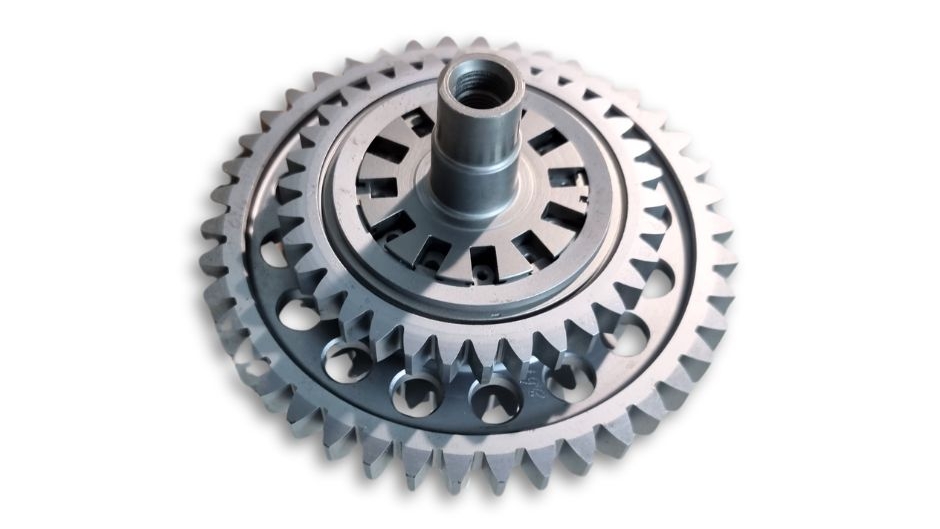
In a typical moment of Duckworth ingenuity, the answer came in ‘cushioning’ the second compound gear, which up to this point had been a rigid assembly. The new design of second compound gear contained 12 small quill shafts that allowed the two side gears to rotate over a limited angular displacement relative to one another, thereby storing some of the huge energy from the cam loadings to successfully reduce the loading on the geartrain.
Crankshaft
Although the first crankshafts were machined from billets, Cosworth quickly switched to fully forged blanks supplied by Smith Clayton Forge. The material for the crankshaft forging was heat treated EN40C 3% chrome molybdenum nitriding steel. After the crankshaft was machined, it was nitrided in an ammonia atmosphere at about 500 C, resulting in a hardened case depth of around 0.015 in (0.38 mm).
The main journals had a diameter of 2.375 in (60.325 mm) and the crank pins were the same as the FVA at 1.938 in (49.2 mm) in diameter, with the crankpins arranged to give a flat-plane layout. The crankshaft weighed 32 lb (14.5 kg), coupled to a flywheel weighing 8 lb (3.6 kg).
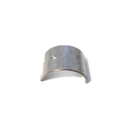
Calculations made during the design of the crankshaft showed that the maximum load would be on the centre main journal, creating a bearing pressure of 6600 psi (45.5 MPa) at 10,500 rpm. The big-end bearing pressures were estimated to be nearly 8000 psi (55.2 MPa). Both the main journal bearings and the big-end bearings were made by Vandervell, from a steel backing with a bronze intermediate layer and a lead indium overlay.
During the early 1970s a Holset-manufactured crank damper was situated on the nose of the crankshaft to reduce torsional vibration. Analysis by both Holset and Vandervell proved that the principal resonance peaks lay between 8,000 and 11,000 rpm. The largest of these peaks was the eighth harmonic excitation of the first order, which occurred at 8,594 rpm, unfortunately in the middle of the running range of the first engines of between 7,000 and 9,500 rpm. The maximum alternating torque was +/- 2,122 lb-ft (2,877 Nm) on the third crankpin, creating a maximum amplitude of +/- 0.95°. The crank damper was removed on later engines in the mid 1970s when the running range was increased away from this peak to 9,000-10,500 rpm.
The crankshaft proved to be an extremely reliable component, but in 1970 there were a series of widely known crank failures. Investigations pointed to a relatively simple grinding error. The corner radii of the crankpin journals were ground both before and after nitriding, but unfortunately the radius on the pre-grinding wheel was too large, which led to the post-nitride grinding wheel going through the nitrided layer, drastically reducing the life of the crankshaft.
Piston & Rings
DFV piston forging material was chosen to be RR58 aluminium alloy (developed by Rolls-Royce). Although this material had a slightly higher thermal expansion coefficient when compared with the high-silicon alloys used on production engine pistons of that era, it remained consistent from 20-200 C. The skirt profile featured tapering along the length of the skirt combined with ovality around the diameter, to provide a diametral skirt clearance of 0.003 in (0.076 mm).
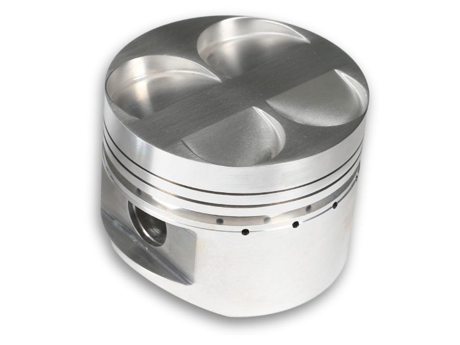
Duckworth sought to minimise the weight of the cast-iron top compression ring, such that the thickness was only 0.030 in (0.76 mm) thick. This would ensure that the ring would stay seated on the bottom face of the piston groove under deceleration and thereby prevent gas leakage past the ring. For the record, the ring gaps were set at 0.017-0.022 in (0.43-0.56 mm).
The gudgeon pin was made from heat treated EN39, case hardened all over, with an outer diameter of 0.813 in (20.6 mm) and an inner diameter of 0.47 in (11.9 mm).
Connecting Rod
Both the rod and the cap were supplied as separate stamped forgings by Smethwick Drop Forgings, using re-melted EN24 steel. The cap was secured to the rod with a pair of 3/8 in (9.525 mm) 12-point big-end bolts, with location provided by two dowel pins. The small-end bush was a steel-backed bronze bearing supplied by Vandervell, finish-bored and honed after assembly. The rod centre distance was 5.230 in (132.84 mm), as Duckworth tried to keep the rod length as long as possible to reduce the secondary out-of-balance forces inherent in a V8 configuration.
Cylinder Heads
The FVA cylinder head featured an included valve angle of 400. Duckworth reduced this further on the DFV to 32° to give a shallower pent-roof chamber and hence a further reduction in surface area and hence less heat loss.
Both the left- and right-hand heads were machined from a common casting. These heads contained 1.32 in (33.5 mm) inlet valves and 1.14 in (29 mm) exhaust valves, both with 7 mm diameter stems. In the middle of the combustion chamber was a 10 mm spark plug. The valve seats and guides were made from aluminium bronze alloys, with 0.003 in (0.076 mm) interference in the head when cold.
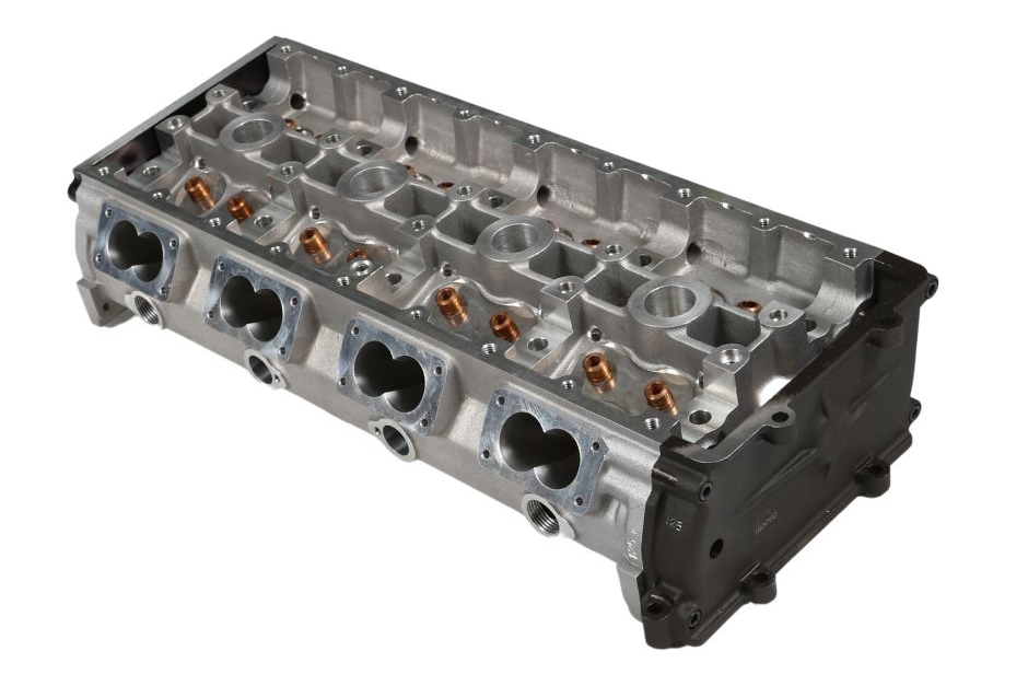
The shape of the inlet ports was kept as straight as possible by Duckworth, with a diameter of 1.02 in (25.9 mm). The ports were fully machined; straight sections were bored, while curved and flared sections into the throats were copy milled. The exhaust ports were completely curved and so had to be copy milled throughout. After machining, the heads were given to the fabled finishing section, where the ports would be polished using a process known as ‘broddling’ within the organisation. It was not uncommon for the finishers to stamp their initials on the side of their cylinder heads so that they could compare dyno test results with each other.
Duckworth had a very rational approach to port design. “I have never believed that there is any point in having a gas flow rig and measuring the flow,” he once said. “I think it is possible to look at the shape of a hole and decide whether the air would like to go through it or not. A hole that looks nice and smooth and has no projections will generally flow easily. Most people start with something so horrible that to create an improvement should be very simple. I would claim that I could arrive at something close to their results from gas flowing just by putting my finger down the hole and seeing what it feels like.”
Camshafts
The camshafts ran in steel-backed white metal shell bearings, again supplied by Vandervell. The bearings were held between dowelled caps and one-piece cam carriers, which like the heads were made from a common casting. Oil was fed up from the main engine gallery into grooves in the middle bearing pairs and then into the hollow camshafts, where it would be directed through drillings in the other cam journals to lubricate the other bearings. The oil from the cam bearings also splash lubricated the tappets, after initial tests showed that feeding oil through holes in the cam lobes was not necessary.
The selected material for the camshafts was EN16T steel, which was liquid nitrocarburized (Tuftride) all over after machining to provide an anti-friction coating. Tappets were machined from EN40, fully ground all over and lapped on the tappet face. The tappets ran directly in the cam carrier, and were 1.25 in (31.75 mm) diameter by 0.9 in (22.9 mm) long.
Understandably, Duckworth paid a lot of attention to the profile of the cam lobes. The Cosworth DFV engine copied most of Cosworth’s other engines of that era and had a lift of 0.410 in (10.4 mm), and symmetrical valve timing with inlet valve opening at 58° before TDC and closing 82° after TDC, exhaust valve opening 82° before BDC and closing 58° after TDC, giving 116° overlap. During build, the tappet clearances were set to 0.010 in (0.254 mm) on the inlet side and 0.015 in (0.38 mm) on the exhaust side.
The ‘Bomb’
In the centre vee of the Cosworth DFV engine lived what Cosworth termed the ‘bomb’, a set of auxiliaries driven from the second compound gear. Within a magnesium centre casting was a Lucas rotating magnet alternator that produced 10 A at 12 V. Also in this assembly was the Lucas Opus ignition system (Oscillating Pick-up System), a plastic drum rotating at half engine speed into which was moulded eight ferrite rods running against a stationary pick-up.
Within the ignition system was a thyristor speed limiter set to 11,300 rpm. This was a standard Lucas product, which Cosworth would then wire into a rubber-mounted box before subjecting it to numerous rig tests to ensure consistent operation over the required speed range, with an overspeed test to check that the speed limiter operated correctly. The trigger disc for the ignition system was mounted on the nose of the crank.
Finally, also in the centre vee was the fuel injection metering unit, again supplied by Lucas. The unit consisted of a stationary hollow sleeve containing a series of radially drilled holes, some of which would feed fuel in from the high-pressure pump and some which would allow fuel out to the injectors mounted in the inlet trumpets. Within the sleeve ran a rotor that also had a corresponding array of radial holes, at selected angles to give the required timing of fuel delivery. Along the centre of the rotor were fuel metering shuttles that oscillated back and forth. A fuel cam that pivoted at the end of the unit controlled the length of the stroke of these shuttles, thereby determining the amount of fuel being delivered. The cam lever was driven by the throttle slides, so that when the throttles were fully open the shuttles could operate a maximum stroke and hence provide maximum fuel delivery to the injectors.
In some of the early races in the late 1960s the Cosworth DFV engine was plagued with fuel vaporisation issues, especially at races in South Africa such as those held at East London and Kyalami. The solution was the rerouting of the return fuel line from the fuel PRV to help cool the fuel.
The Launch of an Icon
The DFV was unveiled by Walter Hayes, public relations director of Ford, at a function at Ford’s Regent Street showrooms on 25th April 1967. In attendance were Keith Duckworth, Lotus founder Colin Chapman and Lotus driver Graham Hill.
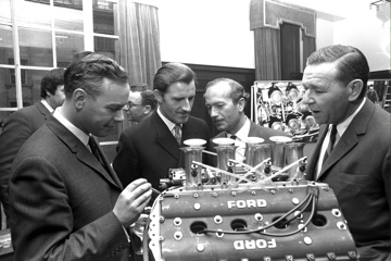
Autosport had this to say about the launch of a new Ford Formula 1 engine: “The announcement this week of the Cosworth-designed and developed Formula 1 engine must be a cause of concern for Lotus’ rivals in the Grande Epreuve field. The compact V8 is extremely light and, as it is designed to do the work of the chassis frame at the rear of the car and carry the suspension, the new Lotus that has been designed around the engine can also be expected to be light and compact. With minimum weight, 400 bhp and Jim Clark and Graham Hill as their drivers, Team Lotus and Ford must be very strong contenders for World Championship victory once they have got their new car sorted out.”
Autosport’s words would prove to be very prophetic – Jim Clark won the first race that the new Lotus 49 powered by the DFV entered in 1967, and Graham Hill took the driver world championship the following year.
Lasting Legacy
The DFV would become the most successful engine ever in the history of Formula One. It went on to win 155 Grand Prix races, 12 driver world championships and 10 constructor championships. It spawned several other winning engine types – the DFW (Tasman Series), DFX (CART/IndyCar from 1975), DFL (Group C), DFY (Formula One from 1983), DFZ (Formula One in 1987), DFR (Formula One from 1988) and the DFS (CART/Indycar from 1988). And its DNA could be traced through subsequent Cosworth Formula One engines and even in the current generation of race engines.
Although numerous developments of the DFV were pursued by Cosworth – including shortened stroke, new cam profiles, changes to the ignition system, redesigned pumps and larger valve diameters – its basic layout never changed. Perhaps this is even more remarkable given that the DFV was the first entire engine designed by Cosworth.
The DFV is still very much alive in historic racing. We continue to support customers rebuilding these engines, supplying a wide range of genuine Cosworth parts along with parts that we’ve been able to reverse engineer and develop. You can find these parts in our on-line shop here: https://modatek.co.uk/product-category/dfv-parts/
This feature on the Cosworth DFV is based on an article written by Modatek’s Matt Grant for Race Engine Technology, issue 84. You can purchase a back copy of this publication here: https://www.highpowermedia.com/Product/race-engine-technology-issue-084

