CON ROD JOINT FACE TECH
One of the critical features of a con rod, and one that is often overlooked, is the joint face. This is the pair of mating faces on the rod and cap halves, and it plays an important role in keeping the con rod together.
In an ideal world there would be no rod and cap halves, and indeed some engine configurations consist of a crankshaft assembly that can be built up from multiple separate sections of crank pin journals and webs. Such an arrangement would then allow for the con rod and big-end bearing to be slid onto the crank pin journal. However, the practicalities of packaging and assembly mean such layouts are only suitable for engines with fewer than four cylinders.
Most race engines will comprise a single-piece crankshaft containing crank pin journals separated by webs and counterbalance weights. So that it can be assembled onto the journals, the rod for each cylinder must consist of a rod half and a cap half.
In most applications, the rod and cap halves both contain plain bearing shells (or in some cases needle roller bearing cages), and these two halves are then bolted together to effectively clamp the bearing. The mating faces of the rod and cap halves are generally termed as the joint face or split line.
Joint Face Design
The correct design of the joint faces of the rod and cap halves is fundamental to the performance and longevity of the con rod assembly. Failure of this joint face will almost certainly lead to a failure of the big-end bolts or bearings, which normally results in a catastrophic engine failure.
Con rod designers will therefore pay close attention to the shape of the joint face, making sure it can withstand both the pre-loading from the big-end bolts and the cyclic loading during engine operation. The design of the rod and cap halves around the split line will have a fundamental effect on the stresses seen by the big-end bolt during these cyclic loads that come about as a result of the reciprocating forces pulling and pushing on the small end of the rod.
A good rule of thumb is that if the stiffness of the housing material around the big-end bolt and at the joint face is increased, the proportion of the cyclic load that the big-end bolt will experience will be reduced. Simply increasing the stiffness around the joint face by adding extra material however isn’t always possible owing to the limited space available – and besides, it will result in a detrimental effect on big-end mass, where every gram matters.
Remember that for static balancing of most crankshaft configurations, every gram on the bottom end of the rod multiplied by the radius of rotation will need a corresponding amount of mass multiplied by radius on the crankshaft balance weight. Any weight saving that can be applied to the bottom end of the rod therefore has a twofold reduction in rotating masses.
Increasing housing stiffness has the beneficial consequence that the bolt size can be reduced, which in turn means the overall size of the joint face can come down. This can lead to an iterative design process to optimise the bolt size and housing stiffness, which is normally carried out either by time-consuming and expensive trial and error or 3D finite element analysis (FEA).
Another key parameter that has to be optimised when designing the joint face is to try to bring the rod bolts inwards and as close to the big-end bore as possible. The major restriction here is the wall section at the joint face between the holes in the rod and cap halves and the big-end bore.
Keeping the big-end bolts as close to the bore as possible makes for a lighter and more compact con rod bottom end, and can reduce the amount of bending load seen in the bolts. Unlike some other classical bolted joint scenarios, big-end bolt loads are not just axial but are a combination of axial and bending loads thanks in part to the oscillatory motion of the bottom end of the rod.
Knowing that pressure is force divided by area, it is clear that the surface pressure seen at the joint face of a rod is greatly influenced by the area of the face. Increasing the joint face area normally means that the surface pressure is lowered, and relatively simple calculations can be derived to determine this pressure as a function of gas and inertia loads combined with the pre-load from tightening the big end bolt.
The effect of housing stiffness and deformation can complicate matters somewhat, which is where FEA can be used to predict surface pressures under different engine operating conditions and at different stages in the two- or four-stroke cycle. There is also the variation in surface pressure across the joint face to consider: the surface pressure can be higher closer to the bolt holes, and is reduced near the big-end bore as the stand-off of the big-end bearings is effectively trying to push the joint faces apart (plain bearings are deliberately designed to be slightly bigger than the housing bore in the con rod so that they are clamped in place when assembled to prevent movement).
Some con rod designs try to minimise this surface pressure variation by adding a very shallow groove or channel in the joint face, running in line with the bolt hole and parallel to the big-end bore axis. This relief can help to raise the pressure at the joint face near the big-end bore to combat the bearing stand-off forces.
Manufacturing the joint faces on both rod and cap halves can be a relatively simple operation if the faces are intended to be flat, but the geometric tolerance of the joint faces with respect to the big-end bore is important, as is the final surface finish.
The joint faces in both halves must be machined before the big-end bore is finished, which can complicate the specification of geometric tolerances; as such, specifications need to pay due regard to the sequential stages of the manufacturing process. Traditionally, joint faces are ground or lapped to achieve a surface finish of around 0.4 Ra. A mirror-like finish isn’t necessary, but conversely a roughened surface is also to be avoided.
Rod & Cap Location
In most cases the rod and cap halves are machined from a forging or billet blank that at some point has to be cut along the split line to allow the joint faces to be machined. Sometimes the rod and cap are actually machined separately, which would be the case if they were made from different materials. Once the joint faces have been machined, the rod and cap halves are then clamped back together with con rod bolts (sometimes referred to as slave bolts) so that the big-end bore can be machined.
It is imperative that after the big-end bore is finished, every time the rod and cap halves are subsequently separated and reassembled they are aligned exactly as they were when the big-end bore was machined. Also, some rods are crank-guided, meaning that they have thrust faces on both sides around the big-end bore to control the lateral movement of the rod along the crank pin journal, and the faces need to remain in their as-machined condition after reassembly.
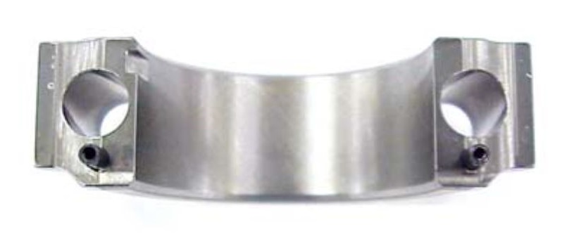
Consequently, the need for the geometry of the big-end bore and thrust faces to remain as close as possible to how they were machined means there must be some method of alignment between the two halves. Many steel and titanium race engine con rods use ring dowels for this alignment.
The ring dowel, or alignment sleeve as it is sometimes called, is pressed into a counter-bore that has been machined into the rod bolt hole in one half, and the dowel then aligns with a matching counter-bore in the other half. Usually the dowel itself is made from a steel alloy, hence both it and (in the case of steel and titanium rods) the surrounding material don’t distort too much when there is a small amount of interference.
This means that repeated removal and assembly of the two halves during manufacture and engine build still gives a repeatable amount of realignment. With an aluminium rod and/or cap half, a steel ring dowel is likely to distort the softer surrounding material, so a serrated joint face is favoured.
One disadvantage of the ring dowel design is that it means having a bigger distance (pitch) between the centres of the big-end bolts, otherwise there won’t be enough wall thickness between the counter-bore on each side for the dowels and the big-end bore. Deleting the counter-bores for the dowels allows the pitch of the bolts to be brought in, which will reduce the bending loads on the bolts, as discussed.
It also allows the width and length of the joint face to be reduced, which in some applications is favourable for packaging the big-end of the rod in confined spaces. That is particularly so in vee engine design, where the designer wants to minimise the bank stagger (the lateral offset distance between the bores on either bank), which brings a knock-on reduction in overall engine length.
Alternatively, a dowel pin on both sides and next to the bolt holes can be used for alignment, and indeed has been a proven robust method for the alignment of rod and cap halves for decades. In an area of the engine where mass is at a premium, some con rods have dowel pins that are less than 4 mm in diameter. Not only does this result in a lighter pin, there is also less material required around the holes in the rod and cap halves. The centre point of the dowel pin hole is carefully chosen to minimise the width and length of the joint face for the reasons already mentioned.
The holes for both ring dowels and dowel pins are relatively easy to machine, and can provide a very good level of realignment tolerance. Traditionally, such holes are slot-drilled first, followed by a reamed hole that can give an ISO H7 tolerance band (in the case of a 4 mm hole, an H7 tolerance band is 12 microns, enough to give a suitable amount of interference with the dowel pin.)
Commercial ring dowels and dowel pins are readily available from numerous suppliers. Dowel pins are normally made from hardened steel or even silver steel in some cases, and the outer diameter is precision ground for excellent roundness tolerances along the entire length of the pin. Sometimes in the case of a solid dowel pin there is the option to include a small, flat section along its length to allow air to escape when the pin in pressed into the blind hole, although this is less common with smaller dowel pins.
Coiled spring pins (sometimes referred to by the tradename Spirol) are an established alternative to the solid variant. They are produced with sufficient control of their diametric tolerance to enable them to align the rod and cap halves but their construction makes them able to absorb shock loads.
Another possibility is to include a shoulder on the big-end bolt, with the shoulder diameter carefully controlled to give a slight interference in the holes in the rod and cap halves. This is only really practical through when the bolt is used in conjunction with a nut.
Joint Face Serrations
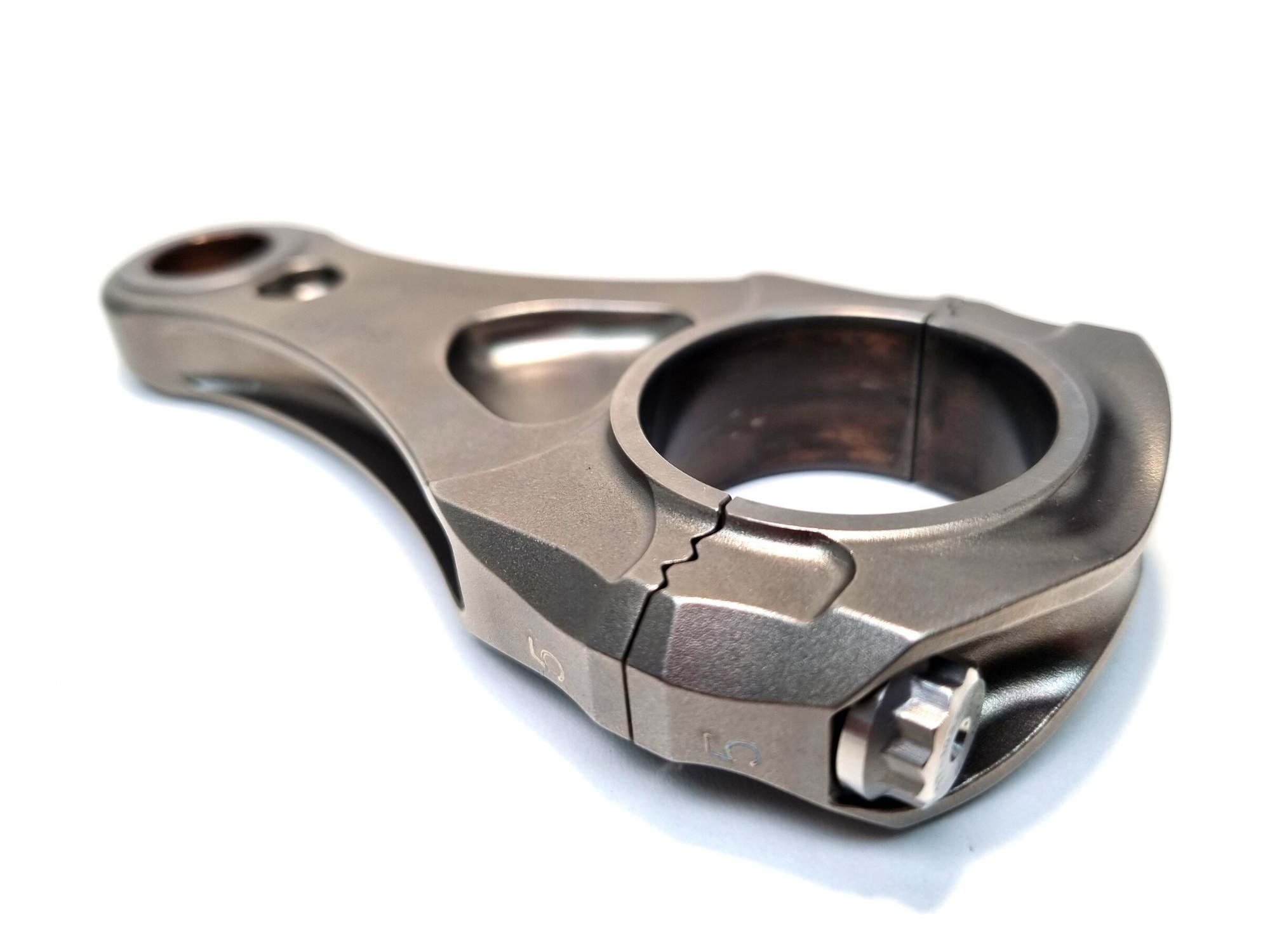
On a conventional flat joint face, in the absence of sufficient pressure, the rod and cap halves can slide, albeit only very slightly but enough to result in fretting damage. But there has been a growing trend towards a new type of joint face: serrated faces, like those on our Cosworth CA2010 con rods.
If machined accurately, serrated faces will be in contact on the flanks of the serrations, restricting any lateral movement and providing a rigid and secure joint. This is particularly important for titanium con rods, as titanium is prone to galling. The flanks of the serrated faces will also have a larger surface area than that for a flat face, which results in a greater contact surface area.
These serrations can increase the housing stiffness around the big-end bore, which can have a beneficial effect on reducing the ovalisation of the big-bore during engine running and can also reduce bending loads on the big-end bolts. The big-end bore will distort into an oval shape when the piston approaches TDC, which can cause wear between the back of the big-end bearings and the con rod big-end bore surface, and create issues with the oil film breaking down between the crank pin journal and the inner diameter of plain bearings.
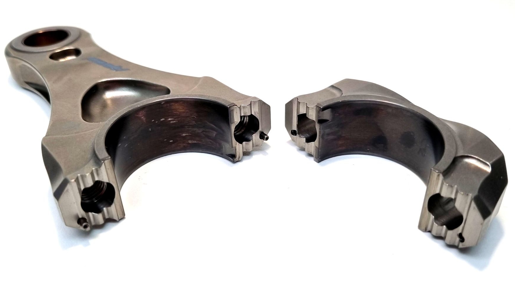
Initially, only straight-cut serrations were available, with the serrations all running in a direction parallel to the big-end bore axis. While that would give good location in one direction, dowel pins or ring dowels would still be needed to give complete alignment, to ensure that the thrust faces on the rod and cap halves were lined up accurately.
Some modern race engine con rods include curved serrations on the joint face that can align the rod and cap halves in all directions, making dowel pins or ring dowels obsolete. The path of the curvature of each serration can vary, but most con rod manufacturers use concentric serrations that are centred at a theoretical point outside the rod. Each side has to have a different centre point, otherwise the rod and cap halves would still be able to rotate about this point, so the designer has to make sure that all degrees of freedom are fixed.
There are numerous ways to machine the serrations on the joint face, including grinding, wire cutting, EDM (electrical discharge machining, also known as spark eroding) and even conventional milling. The actual profiles of the serrations vary between the different con rod manufacturers: some favour more than ten small serrations on each side, others opt for just two or three larger serrations.
The flank angles are nearly always at 45º to the split line to ensure an even distribution of stress in both the rod and cap halves. Understandably, the positional accuracy of the serrations is extremely important if the rod and cap halves are to mate together correctly.
Fracture Splitting
Although more common in the high-volume world of automotive con rods, fracture-split rods are now starting to appear in some race engines. Fracture splitting has been an established process for several decades, and while the method for splitting the rod into the rod and cap halves might seem crude, it actually requires a lot of careful design and process control.
Essentially, a defect is intentionally added to what will become the split line and, with the big end supported, the rod is struck hard enough to split it into two halves. This creates a very high strain rate on the split line, which is enough to make the normally ductile material behave in a brittle manner. This brittleness is necessary as there can’t be any deformation at the split line, so the resultant roughened surface of the joint face is made up of a vast number of peaks and troughs that will locate perfectly when the two halves are reassembled.
This repeatable accuracy in realignment is what makes fracture splitting so appealing for mass production. It means there is no need for dowel pins, ring dowels or serrated faces, thereby reducing cost. It also removes the need to machine or grind the joint faces, which provides another useful cost saving.
The drawback with fracture splitting, and perhaps the reason why it hasn’t become more popular with race engine con rods, is that it is only suitable for certain materials. The rod needs to be made from a material that has a sufficient strain rate sensitivity to allow it to fracture in a brittle manner. Road engine rods that are fracture split are often made from high-carbon wrought steels, as the high carbon composition will lower the content of ductile phases in the steel, but such materials aren’t always suitable for race engine rods.
Recently, some con rod manufacturers have been able to introduce fracture splitting to titanium rods. Titanium might not seem an obvious candidate for fracture splitting because it has a high amount of ductility, especially when compared to most steels. The elongation (a measure of ductility) of titanium alloys that are prevalent in race engine rods can be around 20%, versus around 13% for steel alloys, which means that in most cases titanium is more resistant to fracturing than steel.
The trick to fracture splitting is to find a way to reduce the fracture toughness in the split line zone only, without a detrimental effect on the rest of the rod, where high strength and good elongation properties are still important.
Irrespective of the material chosen, there will also be some sort of feature added from which the crack will initiate, most commonly a small vee-shaped groove or notch where the split line is required. Such notches will allow the crack to propagate and, in the case of the example from Yamaha, move along the grain flow lines that were originally created during the extrusion process.
The final method to weaken the area around the split line is to freeze the con rod in liquid nitrogen, which can take the temperature down to below -200 C. All metals go through a brittle-to-ductile transition as the temperature is lowered (technically this should be termed ductile-to-brittle), and the temperature at which this transition occurs depends on the composition of the metal.
Angled Joint Face
Alongside the radius of the crankshaft web or counterweight, the locus (path) of the heads of the big-end bolt as they move through one complete engine revolution can dictate the height of the sump. A shallow sump can have many benefits for the packaging of the engine, such as enabling the engine to be positioned lower in the car to lower the position of the centre of gravity for better vehicle performance.
In most cases the split line of a conventional con rod will be perpendicular to the rod’s axis, and cut-outs can be added to the engine architecture to clear the rod bolt locus. However, in the quest for better packaging of the bottom end of the engine, some engine designers look to angled joint faces. Angling the split line on the rod can also help to raise the rod bolt locus, thereby permitting the bottom of the sump to move up.
Choosing an angled joint face for a con rod can impose restrictions on the design of the threads in the rod and in the assembly of the big-end bolts. If the rod requires an angled joint face then it is almost certain that the thread will need to be in the rod half, as the big-end bolt will only be able to pass through from the cap half. If the angle of the joint face is severe enough then one of these tapped holes in the rod half will have to be a blind hole.
Although that isn’t necessarily a major problem, it does mean it won’t be possible to measure the stretch of the rod with conventional tooling; in these circumstances, the rod bolt will have to be tightened to an angle instead. As discussed, only a small proportion of the applied torque goes into the pre-load of the bolt, so the rod bolts aren’t normally tightened to a torque figure. To get an accurate and repeatable amount of pre-load, the bolts are normally tightened up to a calculated amount of bolt stretch.
This feature on con rod joint faces is based on an article written by Modatek’s Matt Grant for Race Engine Technology, issue 109. You can purchase a back copy of this publication here: https://www.highpowermedia.com/Product/race-engine-technology-issue-109

